Infiniti G37 Coupe. Manual - part 921


  Index      Infiniti     Infiniti G37 Coupe - service repair manual 2008 year


Search            


Content   ..  919  920  921  922   ..


Infiniti G37 Coupe. Manual - part 921


MWI-30

< FUNCTION DIAGNOSIS >

METER SYSTEM

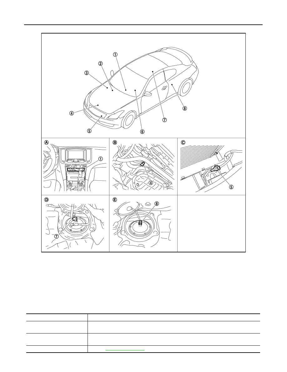
INFORMATION DISPLAY : Component Parts Location

INFOID:0000000001672057

INFORMATION DISPLAY : Component Description

INFOID:0000000001606641

JPNIA0501ZZ

1.

Unified meter and A/C amp.

2.

BCM

3.

IPDM E/R

4.

Oil pressure switch

5.

Ambient sensor

6.

Combination meter

7.

Fuel level sensor unit and fuel pump 
(main)

8.

Fuel level sensor unit (sub)

A.

Behind cluster lid C

B.

Oil pan (upper) RH side

C.

Condenser (front)

D.

Rear seat (lower right)

E.

Rear seat (lower left)

Unit

Description

Combination meter

Controls the information display with the signals received from the unified meter and A/C amp. by 
means of communication and the signals from various switches and sensors.

Unified meter and A/C amp.

Transmits signals received from various units to the combination meter by means of communica-
tion.

Fuel level sensor unit

Refer to 

MWI-54, "Description"

.

MWI

METER SYSTEM

MWI-31

< FUNCTION DIAGNOSIS >

C

D

E

F

G

H

I

J

K

L

M

B

A

O

P

ECM

Transmits the following signals to the unified meter and A/C amp. via CAN communication.

• Engine speed signal

• Fuel consumption monitor signal

ABS actuator and electric unit 
(control unit)

Transmits the vehicle speed signal to the unified meter and A/C amp. via CAN communication.

BCM

Transmits signals provided by various units to the unified meter and A/C amp. via CAN commu-
nication.

Meter control switch

Transmits the following signals to the combination meter.

• Enter switch signal

• Select switch signal

Washer level switch

Transmits the washer level switch signal to the combination meter.

Parking brake switch

Refer to 

MWI-61, "Description"

.

Door switch

Transmits the door switch signals to BCM.

Trunk room lamp switch

Transmits the room lamp switch signal to BCM.

Ambient sensor

Detects the ambient air temperature and transmits the ambient sensor signal to the unified meter 
and A/C amp.

Unit

Description

MWI-32

< FUNCTION DIAGNOSIS >

COMPASS

COMPASS

Description

INFOID:0000000001606642

DISCRIPTION

• This electronic compass is able to display 8 primary directions: N, NE, E, SE, S, SW, W, NW.
• The compass switch (1) is used to operate the compass.

Switch Operation

• All standard compasses determine direction relative to Magnetic North; however, this electronic compass is

designed to display direction relative to True North.

• The difference between Magnetic North and True North varies from place to place across the surface of the

earth.

• This electronic compass must be “told” approximately where it is on the earth’s surface so that the Magnetic

North reading can be properly converted into a True North display.

• To tell the electronic compass where it’s at, the earth is separated into numbered “Zone Variances”. The

Zone Variance number in which the compass is to function must be entered into this electronic compass.

• Each zone is magnetically about 4.2

°

 wide. Typically, anything under 22.5

°

 total zone change is not noticed

on the electronic compass display. However, over 22.5

°

, a reading may be off by one or more primary direc-

tions.

• On long trips, a vehicle may leave its original zone and enter one or more new zones. Generally, you do not

need to reset the compass zone if you travel between 3 or 4 zones, such as business travel or vacation. The
typical driver will not notice any difference on the display within 3 or 4 zones. However, if the vehicle is “per-
manently” moved to a new location, it is recommended that the compass zone be reset.

ZONE VARIATION SETTING PROCEDURE

1.

Press and hold the compass switch for 3 – 9 seconds.

2.

The current zone setting appears on the compass display.

3.

Find the current geographical location number in the Zone Varia-
tion Chart.

4.

Select the new zone number. (Press the compass switch until
the new zone number appears on the compass display.)

5.

After select the new zone number, the compass display will
automatically shows a direction within a few seconds.

6.

Perform the following Calibration Procedure for more accurate
indications.

Press

Compass is turned ON/OFF

Press and hold
(for 3 - 9 sec.)

Compass display (2) turns to zone variation change 
mode Compass

Press and hold (for more 
than 9 sec.)

Compass display turns to calibration mode

SKIB8868E

SEL168Y

MWI

COMPASS

MWI-33

< FUNCTION DIAGNOSIS >

C

D

E

F

G

H

I

J

K

L

M

B

A

O

P

CALIBRATION PROCEDURE

NOTE:
The compass calibrates itself under normal driving conditions. However, occasional circumstances may cause
the compass to operate inaccurately. Example: Driving from rural (wide open) areas to crowded city areas, or
if an aftermarket (i.e., non original equipment) antenna with a magnetic base is attached to the vehicle. Cali-
brate the mirror compass if the display shows only one direction or a limited number of directions.
NOTE:
• If “magnetic hats” are used in the dealership for vehicle identification, remove the hat from the vehicle before

performing the following steps. Do NOT put the hat back on the vehicle after the procedure is completed.

• Drive the vehicle to an open level area; away from large metallic objects, structures, and overhead power

lines.

• Turn off “non-essential” electrical accessories (rear window defrost, heater/air conditioning, wipers) and

close the doors.

1.

Verify the correct compass zone setting for the geographical location.

2.

Press and hold the compass switch for more than 9 seconds.

3.

“C“ is displayed on the compass display, when calibration starts.

4.

Drive slowly [less than 8 km/h (5 MPH)] in a circle until the “C / CAL” is replaced with primary headings (N,
NE, E, SE, S, SW, W, or NW).
NOTE:
This will require driving at least 2 complete 360 degree circles; 3 complete circles may be required.

5.

The compass calibration procedure is now complete. The compass should operate normally.
NOTE:
If at any time the compass continually displays the incorrect direction or the reading is erratic or locked,
repeat the calibration procedure.

Component Parts Location

INFOID:0000000001606643

Special Repair Requirement

INFOID:0000000001606644

1.

PERFORM ZONE VARIATION SETTING

Perform the zone variation setting. Refer to 

MWI-32, "Description"

>> GO TO 2.

2.

PERFORM CALIBRATION

Perform the calibration. Refer to 

MWI-32, "Description"

.

>> Setting completion

1

: Compass switch

2

: Compass display

SKIB8868E


Content   ..  919  920  921  922   ..