Infiniti G37 Coupe. Manual - part 916


  Index      Infiniti     Infiniti G37 Coupe - service repair manual 2008 year


Search            


Content   ..  914  915  916  917   ..


Infiniti G37 Coupe. Manual - part 916


MWI-10

< FUNCTION DIAGNOSIS >

METER SYSTEM

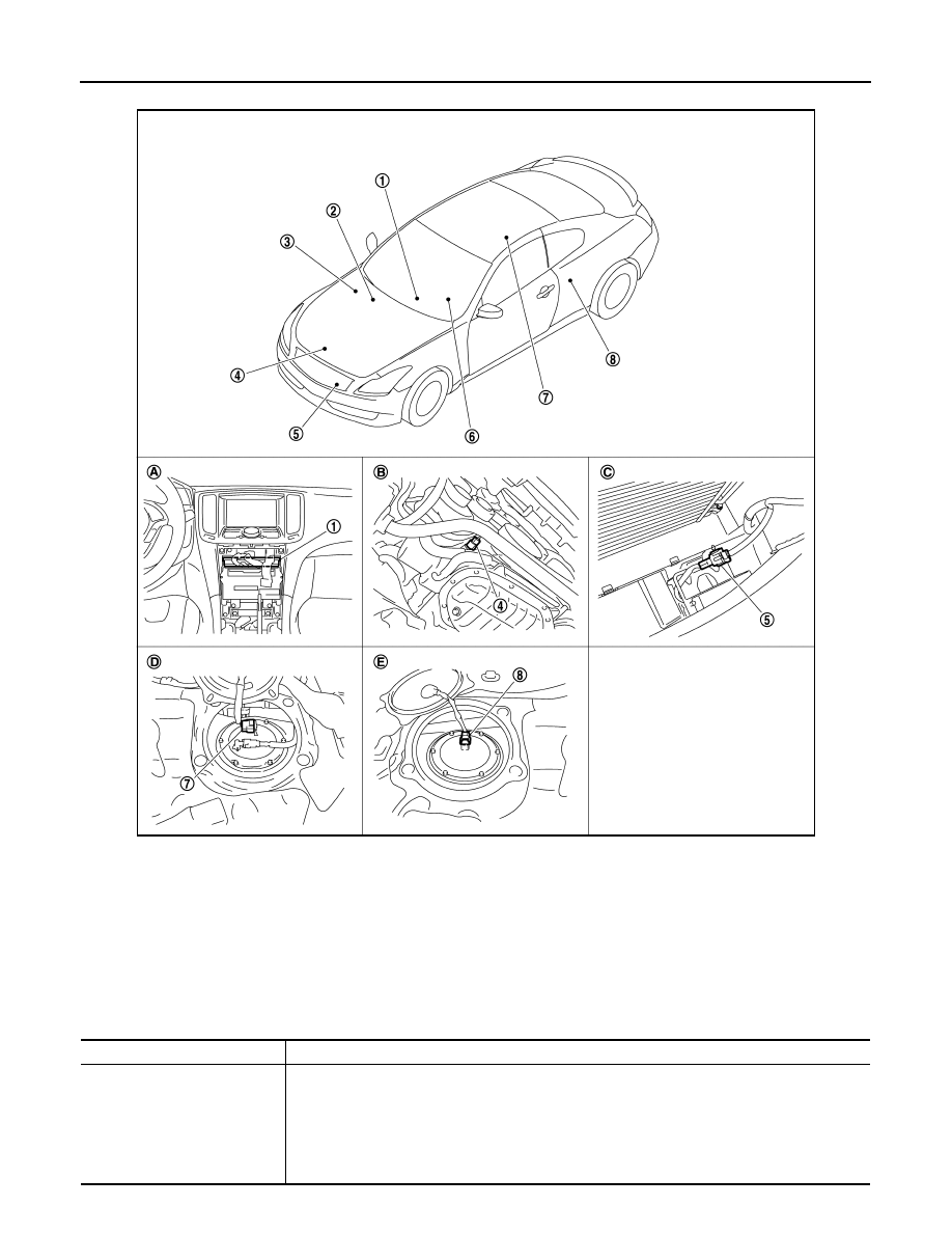
METER SYSTEM : Component Parts Location

INFOID:0000000001606604

METER SYSTEM : Component Description

INFOID:0000000001606605

JPNIA0501ZZ

1.

Unified meter and A/C amp.

2.

BCM

3.

IPDM E/R

4.

Oil pressure switch

5.

Ambient sensor

6.

Combination meter

7.

Fuel level sensor unit and fuel pump 
(main)

8.

Fuel level sensor unit (sub)

A.

Behind cluster lid C

B.

Oil pan (upper) RH side

C.

Condenser (front)

D.

Rear seat (lower right)

E.

Rear seat (lower left)

Unit

Description

Combination meter

Controls the following with the signals from the unified meter and A/C amp, switches and sensors.

• Speedometer

• Tachometer

• Water temperature gauge

• Fuel gauge

• Warning lamps

• Indicator lamps

• Information display

• Warning chime

MWI

METER SYSTEM

MWI-11

< FUNCTION DIAGNOSIS >

C

D

E

F

G

H

I

J

K

L

M

B

A

O

P

SPEEDOMETER

SPEEDOMETER : System Diagram

INFOID:0000000001606606

SPEEDOMETER : System Description

INFOID:0000000001606607

• The ABS actuator and electric unit (control unit) converts the pulse signal provided by the wheel sensor to a

vehicle speed signal and transmits it to the unified meter and A/C amp. with CAN communication line.

• The unified meter and A/C amp. receives the vehicle speed signal from the ABS actuator and electric unit

(control unit) with CAN communication line and transmits it to the combination meter by means of communi-
cation line.

• The combination meter indicates the vehicle speed according to the vehicle speed signal received from the

unified meter and A/C amp. by means of communication line.

Unified meter and A/C amp.

• The combination meter receives the necessary information from various units via CAN communi-

cation line and transmits them to the unified meter and A/C amp. with the communication line that 
connects both of them.

• Transmits the fuel gauge signal from the fuel gauge unit with the communication line that connects 

the unified meter and A/C amp. and the combination meter.

• Reads the signals from the A/T device and paddle shifter and transmits them to TCM with CAN 

communication line.

IPDM E/R

IPDM E/R reads the ON/OFF signals of the oil pressure switch and transmits the oil pressure switch 
signal to the unified meter and A/C amp. via BCM with CAN communication line.

Fuel level sensor unit

Refer to 

MWI-54, "Description"

.

Oil pressure switch

Refer to 

MWI-59, "Description"

.

ECM

Transmits the following signals to the unified meter and A/C amp. with CAN communication line.

• Engine speed signal

• Engine coolant temperature signal

• Fuel consumption monitor signal

ABS actuator and electric unit 
(control unit)

Transmits the vehicle speed signal to the unified meter and A/C amp. with CAN communication line.

BCM

• Transmits signals provided by various units to the unified meter and A/C amp. with CAN commu-

nication line.

• Transmits the security signal to the combination meter.

A/T device

Transmits the following signals to the unified meter and A/C amp.

• Manual mode signal

• Not manual mode signal

• Manual mode shift up signal

• Manual mode shift down signal

Paddle shifter

Transmits the paddle shifter up signal and paddle shifter down signal to the unified meter and A/C 
amp.

TCM

Transmits shift position signal to the unified meter and A/C amp.

Meter control switch

Refer to 

MWI-57, "Description"

.

Washer level switch

Transmits the washer level switch signal to the combination meter.

Brake fluid level switch

Transmits the brake fluid level switch signal to the combination meter.

Parking brake switch

Refer to 

MWI-61, "Description"

.

Unit

Description

JSNIA0611GB

MWI-12

< FUNCTION DIAGNOSIS >

METER SYSTEM

SPEEDOMETER : Component Parts Location

INFOID:0000000001672037

SPEEDOMETER : Component Description

INFOID:0000000001606609

JPNIA0501ZZ

1.

Unified meter and A/C amp.

2.

BCM

3.

IPDM E/R

4.

Oil pressure switch

5.

Ambient sensor

6.

Combination meter

7.

Fuel level sensor unit and fuel pump 
(main)

8.

Fuel level sensor unit (sub)

A.

Behind cluster lid C

B.

Oil pan (upper) RH side

C.

Condenser (front)

D.

Rear seat (lower right)

E.

Rear seat (lower left)

Unit

Description

Combination meter

Indicates the vehicle speed according to the vehicle speed signal received from the unified meter 
and A/C amp. by means of communication line.

Unified meter and A/C amp.

Transmits the vehicle speed signal received from ABS actuator and electric unit (control unit) with 
CAN communication line to the combination meter by means of communication line.

ABS actuator and electric unit 
(control unit)

Transmits the vehicle speed signal to the unified meter and A/C amp. with CAN communication 
line.

MWI

METER SYSTEM

MWI-13

< FUNCTION DIAGNOSIS >

C

D

E

F

G

H

I

J

K

L

M

B

A

O

P

TACHOMETER

TACHOMETER : System Diagram

INFOID:0000000001606610

TACHOMETER : System Description

INFOID:0000000001606611

• ECM converts the pulse signal provided by the crankshaft position sensor to an engine speed signal and

transmits it to the unified meter and A/C amp. with CAN communication line.

• Unified meter and A/C amp. transmits engine speed signal to combination meter with communication line.
• The unified meter and A/C amp. receives the engine speed signal from ECM with CAN communication line

and transmits it to the combination meter by means of communication line.

• Combination meter converses engine speed signal to the angle signal, and commands to tachometer.

JSNIA0160GB


Content   ..  914  915  916  917   ..