Infiniti G37 Coupe. Manual - part 829


  Index      Infiniti     Infiniti G37 Coupe - service repair manual 2008 year


Search            


Content   ..  827  828  829  830   ..


Infiniti G37 Coupe. Manual - part 829


INSTRUMENT PANEL ASSEMBLY

IP-17

< ON-VEHICLE REPAIR >

C

D

E

F

G

H

I

K

L

M

A

B

IP

N

O

P

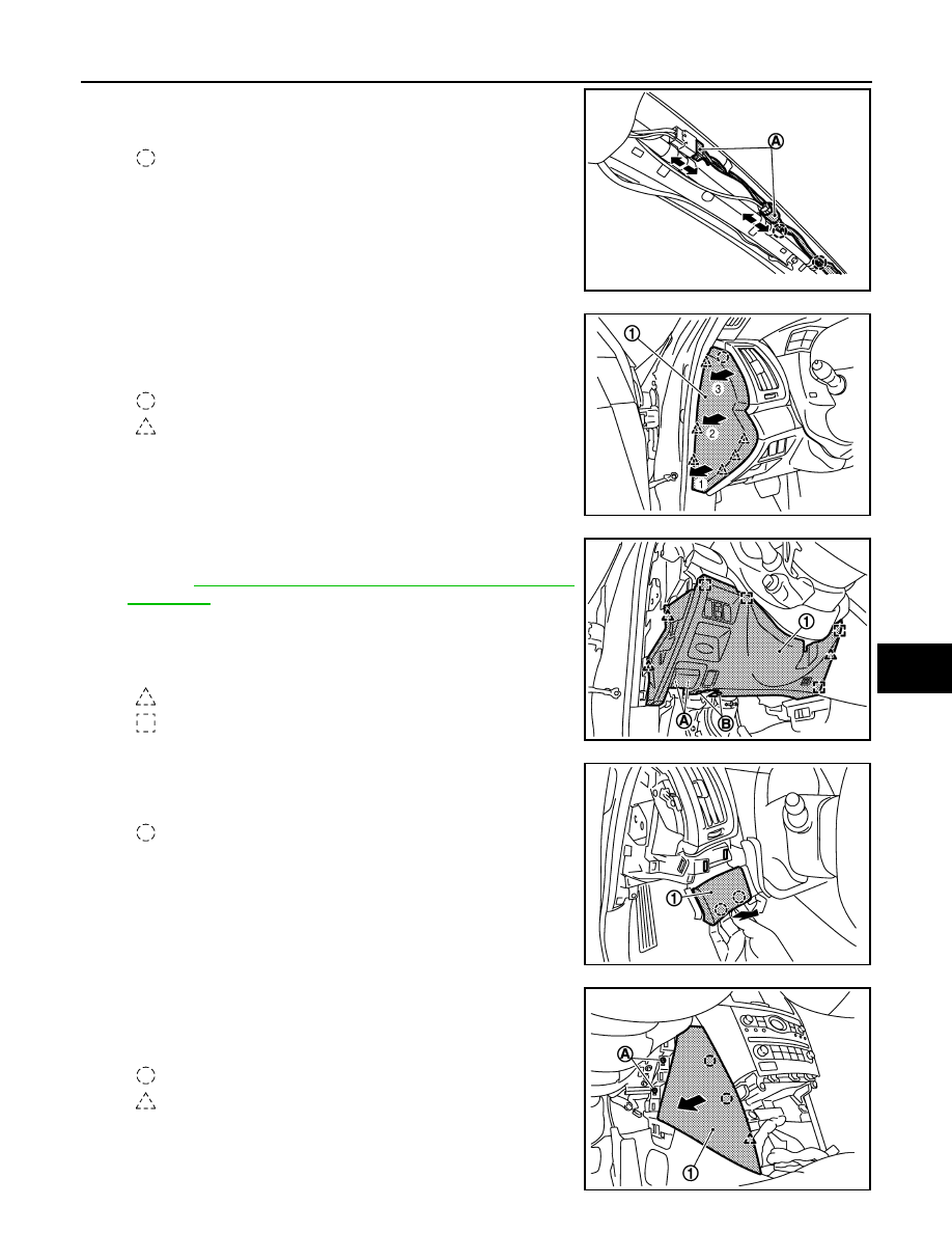
24. Disconnect antenna harness connectors (A) and then remove

harness clips.

25. Remove instrument side finisher LH.

• Insert a remover tool into lower space.
• Pull the instrument side finisher LH (1) crosswise.

26. Remove instrument driver lower panel.

• Remove hood opener mounting bolts (A). 

Refer to 

DLK-211, "HOOD LOCK CONTROL : Removal and

Installation"

.

• Remove data link connector mounting screws (B). 
• Pull back instrument driver lower panel (1).
• Disconnect harness connectors.

27. Remove instrument finisher A. 

Pull instrument finisher A (1) upward, and then disengage pawls.

28. Remove instrument side panel LH.

• Remove instrument side panel mounting screw (A).
• Pull the instrument side panel LH (1) crosswise.

: Clip

JMJIA0102GB

: Clip

: Pawl

JMJIA0040GB

: Pawl

: Metal clip

JMJIA0041GB

: Clip

JMJIA0053GB

: Clip

: Pawl

JMJIA0042GB

IP-18

< ON-VEHICLE REPAIR >

INSTRUMENT PANEL ASSEMBLY

29. Remove steering wheel assembly. Refer to 

ST-15, "Removal and Installation"

.

30. Remove steering column covers.

CAUTION:

When removing the column covers, to facilitate the work operation remove first the steering
wheel. 

• Remove steering column front lower cover (1).
• Remove cluster lid A lower bracket (2).

• Remove steering column mask (3) and screws.
• Pull up steering column cover upper (4).
• Remove steering column side cover RH (5) (with PADDLE SHIFTER).
• Pull the steering column side cover LH (6) to the left side (with PADDLE SHIFTER). 
• Disconnect ADP steering switch connector (with ADP).
• Remove steering column side cover LH (6).
• Remove screws, and then remove steering column lower cover (7).

31. Remove spiral cable and steering angle sensor. Refer to 

SR-7, "Removal and Installation"

.

CAUTION:

Perform 4WAS front actuator adjustment. Refer to 

STC-27, "4WAS FRONT ACTUATOR NEUTRAL

POSITION ADJUSTMENT : Description"

32. Remove combination switch. Refer to 

BCS-80, "Removal and Installation"

.

33. Remove paddle switch LH/RH (with PADDLE SHIFTER). Refer to 

TM-230, "Removal and Installation"

.

34. Remove cluster lid A.

(A)

Column cover (with electric column)

(B)

Column cover (with manual column)

(A)

Column cover (with PADDLE SHIFTER)

(B)

Column cover (without PADDLE SHIFTER)

: Pawl

JMJIA0047GB

JMJIA0048GB

INSTRUMENT PANEL ASSEMBLY

IP-19

< ON-VEHICLE REPAIR >

C

D

E

F

G

H

I

K

L

M

A

B

IP

N

O

P

• Remove knee protector mounting bolts (A) with power tool,

and then remove knee protector (1).

• Disengage harness cover mounting pawl (B) by using tool (A)

located under the column shaft.

• Pull down harness cover (1).

(with harness cover)

• Remove cluster lid A (combination meter) mounting bolts (A).

• Disconnect push button ignition switch harness connector (A). 

• Pull back cluster lid A, and disconnect combination meter connectors.

JMJIA0064GB

JMJIA0049GB

JMJIA0050GB

JMJIA0051GB

IP-20

< ON-VEHICLE REPAIR >

INSTRUMENT PANEL ASSEMBLY

35. Remove meter bracket mounting bolts (A), and then remove

meter bracket (1).

36. Remove defroster grille LH. Refer to 

VTL-45, "FRONT DEFROSTER NOZZLE, SIDE DEFROSTER NOZ-

ZLE AND VENTILATOR DUCT : Exploded View"

.

• Pull upward, disengage pawls.
• Disconnect harness connector.

37. Remove defroster grille RH. Refer to 

VTL-45, "FRONT DEFROSTER NOZZLE, SIDE DEFROSTER NOZ-

ZLE AND VENTILATOR DUCT : Exploded View"

.

• Pull upward, disengaged pawls.
• Disconnect harness connector.

38. Remove body side welt RH. Refer to 

INT-14, "Removal and Installation"

.

39. Remove front pillar garnish RH. Refer to 

INT-14, "Removal and Installation"

.

40. Remove instrument side finisher RH.

• Insert a remover tool into lower space.
• Pull the instrument side finisher RH (1) crosswise.

41. Remove instrument passenger lower cover.

• Pull downward, disengaged pawls. 
• Pull back instrument passenger lower cover (1).

42. Remove glove box assembly.

• Open the glove box. 

JMJIA0052GB

: Clip

: Pawl

JMJIA0054GB

: Pawl

JMJIA0055GB


Content   ..  827  828  829  830   ..