Infiniti G37 Coupe. Manual - part 780


  Index      Infiniti     Infiniti G37 Coupe - service repair manual 2008 year


Search            


Content   ..  778  779  780  781   ..


Infiniti G37 Coupe. Manual - part 780


ECM

HAC-109

< ECU DIAGNOSIS >

[AUTOMATIC AIR CONDITIONER]

C

D

E

F

G

H

J

K

L

M

A

B

HAC

N

O

P

21

(GR)

128

(B)

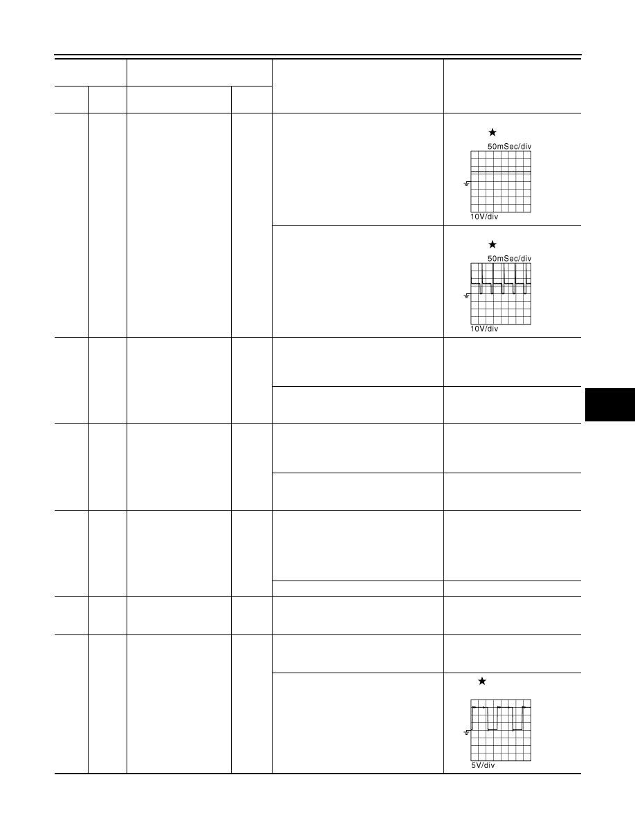
EVAP canister purge vol-
ume control solenoid 
valve

Output

[Engine is running]
• Idle speed
• Accelerator pedal: Not depressed even 

slightly, after engine starting

BATTERY VOLTAGE

(11 - 14V)

[Engine is running]
• Engine speed: About 2,000 rpm (More 

than 100 seconds after starting engine)

BATTERY VOLTAGE

(11 - 14V)

22

(R)

128

(B)

Fuel pump relay

Output

[Ignition switch: ON]
• For 1 second after turning ignition switch 

ON

[Engine is running]

0 - 1.5V

[Ignition switch: ON]
• More than 1 second after turning ignition 

switch ON

BATTERY VOLTAGE
(11 - 14V)

24

(P)

128

(B)

ECM relay
(Self shut-off)

Output

[Engine is running]
[Ignition switch: OFF]
• A few seconds after turning ignition 

switch OFF

0 - 1.5V

[Ignition switch: OFF]
• More than a few seconds after turning 

ignition switch OFF

BATTERY VOLTAGE
(11 - 14V)

25

(O)

128

(B)

Throttle control motor re-
lay

Output

[Ignition switch: ON 

 OFF]

0 - 1.0V 

BATTERY VOLTAGE 
(11 - 14V) 

0V

[Ignition switch: ON]

0 - 1.0V

28

(BR)

128

(B)

VVEL actuator motor re-
lay abort signal
[VVEL control module]

Output

[Engine is running]
• Warm-up condition
• Idle speed

0V

29

(G)

128

(B)

Intake valve timing con-
trol solenoid valve (bank 
2)

Output

[Engine is running]
• Warm-up condition
• Idle speed

BATTERY VOLTAGE
(11 - 14V)

[Engine is running]
• Warm-up condition
• Engine speed: 2,000rpm

7 - 12V

Terminal No.

(Wire color)

Description

Condition

Value

(Approx.)

+

-–

Signal  name

Input/

Output

JMBIA0039GB

JMBIA0040GB

JMBIA0038GB

HAC-110

< ECU DIAGNOSIS >

[AUTOMATIC AIR CONDITIONER]

ECM

30

(Y)

40

(R)

Throttle position sensor 
1 (bank 1)

Input

[Ignition switch: ON]
• Engine stopped
• Selector lever: D (A/T) or 1st (M/T)
• Accelerator pedal: Fully released

More than 0.36V

[Ignition switch: ON]
• Engine stopped
• Selector lever: D (A/T) or 1st (M/T)
• Accelerator pedal: Fully depressed

Less than 4.75V

31

(R)

48

(B)

Throttle position sensor 
1 (bank 2)

Input

[Ignition switch: ON]
• Engine stopped
• Selector lever: D (A/T) or 1st (M/T)
• Accelerator pedal: Fully released

More than 0.36V

[Ignition switch: ON]
• Engine stopped
• Selector lever: D (A/T) or 1st (M/T)
• Accelerator pedal: Fully depressed

Less than 4.75V

33

(SB)

128

(B)

Heated oxygen sensor 2 
heater (bank 2)

Output

[Engine is running]
• Engine speed: Below 3,600 rpm after 

the following conditions are met

- Engine: after warming up
- Keeping the engine speed between 

3,500 and 4,000 rpm for 1 minute and at 
idle for 1 minute under no load

10V

[Ignition switch: ON]
• Engine stopped
[Engine is running]
• Engine speed: Above 3,600 rpm

BATTERY VOLTAGE
(11 - 14V)

34

(B)

40

(R)

Throttle position sensor 
2 (bank 1)

Input

[Ignition switch: ON]
• Engine stopped
• Selector lever: D (A/T) or 1st (M/T)
• Accelerator pedal: Fully released

Less than 4.75V

[Ignition switch: ON]
• Engine stopped
• Selector lever: D (A/T) or 1st (M/T)
• Accelerator pedal: Fully depressed

More than 0.36V

35

(W)

48

(B)

Throttle position sensor 
2 (bank 2)

Input

[Ignition switch: ON]
• Engine stopped
• Selector lever: D (A/T) or 1st (M/T)
• Accelerator pedal: Fully released

Less than 4.75V

[Ignition switch: ON]
• Engine stopped
• Selector lever: D (A/T) or 1st (M/T)
• Accelerator pedal: Fully depressed

More than 0.36V

36

(O)

Sensor ground
[Brake booster pressure 
sensor]

Terminal No.

(Wire color)

Description

Condition

Value

(Approx.)

+

-–

Signal name

Input/

Output

JMBIA0037GB

ECM

HAC-111

< ECU DIAGNOSIS >

[AUTOMATIC AIR CONDITIONER]

C

D

E

F

G

H

J

K

L

M

A

B

HAC

N

O

P

37

(W)

128

(B)

Crankshaft position sen-
sor (POS)

Input

[Engine is running]
• Warm-up condition
• Idle speed

NOTE:
The pulse cycle changes depending on 
rpm at idle

4.0 - 5.0

[Engine is running]
• Engine speed: 2,000 rpm

4.0 - 5.0

38

(O)

96

(P)

Manifold absolute pres-
sure (MAP) sensor

Input

[Engine is running]
• Warm-up condition
• Idle speed

1.2V

[Engine is running]
• Warm-up condition
• Engine speed: 2,000 rpm

1.5V

39

(P)

36

(O)

Brake booster pressure 
sensor

Input

[Engine is running]
• Warm-up condition
• Idle speed
• Brake pedal: Fully released

1.2V

[Engine is running]
• Warm-up condition
• Idle speed
• Brake pedal: Fully depressed

3.0V

40

(R)

Sensor ground
[Throttle position sensor 
(bank 1)]

43

(G)

48

(B)

Sensor power supply
[Throttle position sensor 
(bank 2)]

[Ignition switch: ON]

5V

44

(L)

40

(R)

Sensor power supply
[Throttle position sensor 
(bank 1)]

[Ignition switch: ON]

5V

45

(LG)

36

(O)

Sensor power supply
[Brake booster pressure 
sensor]

[Ignition switch: ON]

5V

46

(R)

128

(B)

Sensor power supply
[Crankshaft position 
sensor (POS)]

[Ignition switch: ON]

5V

47

(Y)

Sensor ground
[Crankshaft position 
sensor (POS)]

48

(B)

Sensor ground
[Throttle position sensor 
(bank 2)]

Terminal No.

(Wire color)

Description

Condition

Value

(Approx.)

+

-–

Signal  name

Input/

Output

JMBIA0041GB

JMBIA0042GB

HAC-112

< ECU DIAGNOSIS >

[AUTOMATIC AIR CONDITIONER]

ECM

49

(GR)

128

(B)

Throttle control motor 
(Close) (bank 2)

Output

[Ignition switch: ON]
• Engine stopped
• Selector lever: D (A/T) or 1st (M/T)
• Accelerator pedal: In the middle of re-

leasing operation

0 - 14V

50

(V)

128

(B)

Throttle control motor 
(Open) (bank 2)

Output

[Ignition switch: ON]
• Engine stopped
• Selector lever: D (A/T) or 1st (M/T)
• Accelerator pedal: Fully depressed

0 - 14V

[Ignition switch: ON]
• Engine stopped
• Selector lever: D (A/T) or 1st (M/T)
• Accelerator pedal: Fully released

0 - 14V

52

(R)

128

(B)

Throttle control motor re-
lay power supply (bank 
2)

Input

[Ignition switch: ON]

BATTERY VOLTAGE
(11 - 14V)

53

(W)

128

(B)

Ignition switch

Input

[Ignition switch: OFF]

0V

[Ignition switch: ON]

BATTERY VOLTAGE
(11 - 14V)

54

(Y)

CAN communication line
[VVEL control module]

Input/

output

55

(LG)

CAN communication line
[VVEL control module]

Input/

output

57

(L)

128

(B)

A/F sensor 1 (bank 1)

Input

[Ignition switch: ON]

2.2V

59

(O)

128

(B)

Camshaft position sen-
sor (PHASE) (bank 1)

Input

[Engine is running]
• Warm-up condition
• Idle speed

NOTE:
The pulse cycle changes depending on 
rpm at idle

3.0 - 5.0

[Engine is running]
• Engine speed: 2,000 rpm

3.0 - 5.0

Terminal No.

(Wire color)

Description

Condition

Value

(Approx.)

+

-–

Signal name

Input/

Output

JMBIA0033GB

JMBIA0031GB

JMBIA0032GB

JMBIA0045GB

JMBIA0046GB


Content   ..  778  779  780  781   ..