Infiniti G37 Coupe. Manual - part 773


  Index      Infiniti     Infiniti G37 Coupe - service repair manual 2008 year


Search            


Content   ..  771  772  773  774   ..


Infiniti G37 Coupe. Manual - part 773


BLOWER MOTOR

HAC-81

< COMPONENT DIAGNOSIS >

[AUTOMATIC AIR CONDITIONER]

C

D

E

F

G

H

J

K

L

M

A

B

HAC

N

O

P

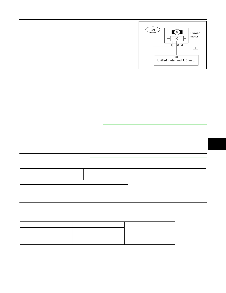
Blower motor circuit

WITH LEFT AND RIGHT VENTILATION TEMPERATURE SEPARATELY CONTROL 
SYSTEM : Component Function Check

INFOID:0000000001675710

1.

CONFIRM SYMPTOM BY PERFORMING THE FOLLOWING OPERATIONAL CHECK

1.

Start engine and warm it up to normal operating temperature.

2.

Press fan (UP: +) switch. Blower should operate on low speed.

3.

Press fan (UP: +) switch, and continue checking blower speed and fan symbol until all speeds checked.

Is the inspection result normal?

YES

>> END.

NO

>> Go to diagnosis procedure. Refer to 

HAC-81, "WITH LEFT AND RIGHT VENTILATION TEMPER-

ATURE SEPARATELY CONTROL SYSTEM : Diagnosis Procedure"

.

WITH LEFT AND RIGHT VENTILATION TEMPERATURE SEPARATELY CONTROL 
SYSTEM : Diagnosis Procedure

INFOID:0000000001675711

1.

PERFORM SELF-DIAGNOSIS STEP-4

Perform self-diagnosis STEP-4. Refer to 

HAC-48, "WITH LEFT AND RIGHT VENTILATION TEMPERATURE

SEPARATELY CONTROL SYSTEM : Diagnosis Description"

, see Nos. 1 to 5.

Does blower motor speed change according to each code No.?

YES

>> END.

NO

>> GO TO 2.

2.

CHECK POWER SUPPLY FOR BLOWER MOTOR

1.

Disconnect blower motor connector.

2.

Turn ignition switch ON.

3.

Check voltage between blower motor harness connector and ground.

Is the inspection result normal?

YES

>> GO TO 3.

NO

>> GO TO 6.

3.

CHECK BLOWER MOTOR GROUND CIRCUIT

1.

Turn ignition switch OFF.

2.

Check continuity between blower motor harness connector and ground.

JSIIA0779GB

Code  No.

41

42

43

44

45

46

Blower motor duty ratio

37%

91%

65%

91%

(+)

(

)

Voltage

Blower motor

Connector

Terminal

M109

1

Ground

Battery voltage

HAC-82

< COMPONENT DIAGNOSIS >

[AUTOMATIC AIR CONDITIONER]

BLOWER MOTOR

Is the inspection result normal?

YES

>> GO TO 4.

NO

>> Repair harness or connector.

4.

CHECK CIRCUIT CONTINUITY BETWEEN BLOWER MOTOR AND UNIFIED METER AND A/C AMP.

1.

Disconnect unified meter and A/C amp. connector.

2.

Check continuity between blower motor harness connector and unified meter and A/C amp. harness con-
nector.

3.

Check continuity between blower motor harness connector and ground.

Is the inspection result normal?

YES

>> GO TO 5.

NO

>> Repair harness or connector.

5.

CHECK UNIFIED METER AND A/C AMP. OUTPUT SIGNAL

1.

Reconnect blower motor connector and unified meter and A/C amp. connector.

2.

Turn ignition switch ON.

3.

Set MODE switch to VENT position.

4.

Change fan speed from Lo to Hi, and check duty ratios between blower motor harness connector M109
terminal 2 and ground by using an oscilloscope. Normal terminal 2 drive signal duty ratios are shown in
the table below.

Is the inspection result normal?

YES

>> Check blower motor. Refer to 

HAC-83, "WITH LEFT AND RIGHT VENTILATION TEMPERA-

TURE SEPARATELY CONTROL SYSTEM : Component Inspection"

.

NO

>> Replace unified meter and A/C amp.

blower motor

Continuity

Connector

Terminal

M109

3

Ground

Existed

blower motor

Unified meter and A/C amp.

Continuity

Connector

Terminal

Connector

Terminal

M109

2

M66

38

Existed

blower motor

Continuity

Connector

Terminal

M109

2

ground

Not existed

JSIIA0068GB

BLOWER MOTOR

HAC-83

< COMPONENT DIAGNOSIS >

[AUTOMATIC AIR CONDITIONER]

C

D

E

F

G

H

J

K

L

M

A

B

HAC

N

O

P

6.

CHECK POWER VOLTAGE OF BLOWER FAN MOTOR

Check the voltage between fuse block connector and ground. Refer to 

PG-91, "Fuse, Connector and Terminal

Arrangement"

.

Is the inspection result normal?

YES

>> Repair harness or connector [between fuse block (J/B) and blower fan motor].

NO

>> GO TO 7.

7.

CHECK POWER VOLTAGE OF BLOWER RELAY

Check the voltage between fuse block (J/B) connector and ground. Refer to 

PG-91, "Fuse, Connector and Ter-

minal Arrangement"

.

Is the inspection result normal?

YES

>> GO TO 8.

NO

>> GO TO 9.

8.

CHECK FUSE

Check fuse 15A [Nos 21 and 22, located in the fuse block (J/B). Refer to 

PG-91, "Fuse, Connector and Termi-

nal Arrangement"

.

Is the inspection result normal?

YES

>> Replace blower relay.

NO

>> Be sure to eliminate cause of malfunction before installing new fuse.

9.

CHECK POWER VOLTAGE OF BLOWER RELAY (BCM)

Check the voltage between fuse block (J/B) connector and ground.

Is the inspection result normal?

YES

>> Repair harness or connector (between BCM and fuse block).

NO

>> Check ignition power supply. Refer to 

PCS-73, "Diagnosis Procedure"

.

WITH LEFT AND RIGHT VENTILATION TEMPERATURE SEPARATELY CONTROL 
SYSTEM : Component Inspection

INFOID:0000000001713995

1.

CHECK BLOWER MOTOR

(+)

(

)

Voltage

Fuse block (J/B)

Connector

Terminal

M1

3A

Ground

Battery voltage

8A

(+)

(

)

Voltage

Fuse block (J/B)

Connector

Terminal

E103

6F

Ground

Battery voltage

(+)

(

)

Voltage

BCM

Connector

Terminal

M122

102

Ground

Battery voltage

HAC-84

< COMPONENT DIAGNOSIS >

[AUTOMATIC AIR CONDITIONER]

BLOWER MOTOR

1.

Remove blower motor (1).

2.

Confirm smooth rotation of the blower motor.

Is the inspection result normal?

YES

>> END.

NO

>> Replace blower motor.

JSIIA0044ZZ


Content   ..  771  772  773  774   ..