Infiniti G37 Coupe. Manual - part 765


  Index      Infiniti     Infiniti G37 Coupe - service repair manual 2008 year


Search            


Content   ..  763  764  765  766   ..


Infiniti G37 Coupe. Manual - part 765


DIAGNOSIS SYSTEM (AUTO AMP.)

HAC-49

< FUNCTION DIAGNOSIS >

[AUTOMATIC AIR CONDITIONER]

C

D

E

F

G

H

J

K

L

M

A

B

HAC

N

O

P

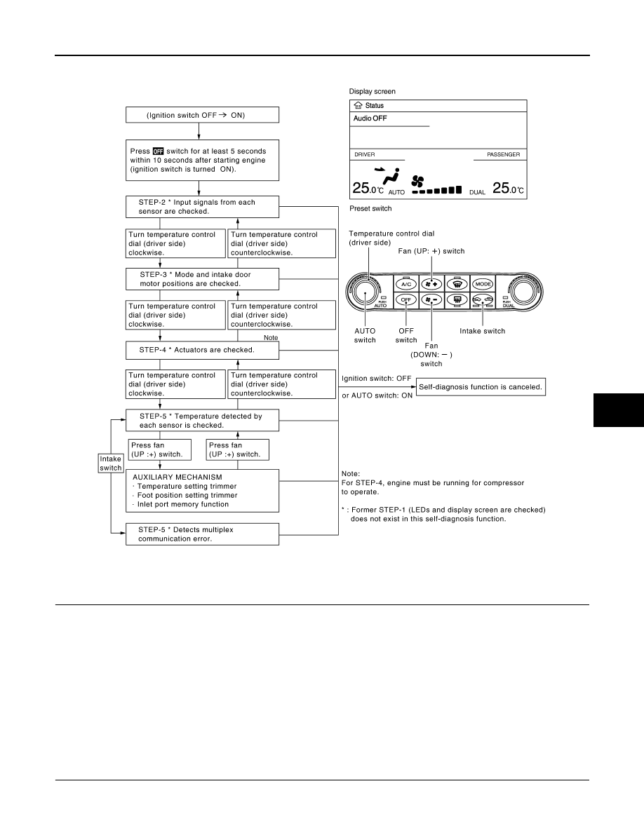
Shifting from STEP-5 to AUXILIARY MECHANISM is accomplished by means of pressing fan (UP:+) switch.

CONFORMATION METHOD

1.

SET IN SELF-DIAGNOSIS MODE

1.

Turn ignition switch ON.

2.

Set in self-diagnosis mode as per the following. Press OFF switch for at least 5 seconds Within 10 sec-
onds after starting engine (ignition switch is turned ON).

NOTE:
• If battery voltage drops below 12 V during diagnosis STEP-3, door motor speed becomes slower and as a

result, the system may generate an error even when operation is normal. Start engine before performing this
diagnosis to avoid this.

• Former STEP-1 (LEDs and display screen are checked) does not exist in this self-diagnosis function.
• OFF switch may not be recognized according to the timing of pressing it. Operate OFF switch after turning

the intake switch LEDs (REC/FRE) ON.

>> GO TO 2.

2.

STEP-2: SENSOR AND DOOR MOTOR CIRCUITS ARE CHECKED FOR OPEN OR SHORT CIRCUIT

JSIIA0771GB

HAC-50

< FUNCTION DIAGNOSIS >

[AUTOMATIC AIR CONDITIONER]

DIAGNOSIS SYSTEM (AUTO AMP.)

Does code No. 20 appear on the display?

YES

>> GO TO 3.

NO

>> GO TO 11.

3.

STEP-3: MODE DOOR AND INTAKE DOOR POSITIONS ARE CHECKED

Turn temperature control dial (driver side) clockwise.

Does code No. 30 appear on the display?

YES

>> GO TO 4.

NO

>> GO TO 12.

4.

STEP-4: OPERATION OF EACH DOOR MOTOR IS CHECKED

1.

Turn temperature control dial (driver side) clockwise.

2.

Press DEF (

) switch. Code No. of each door motor test is

indicated on the display.

>> GO TO 5.

5.

CHECK ACTUATORS

Refer to the following chart and check discharge air flow, air temperature, blower motor duty ratio and com-
pressor operation.

SJIA1778E

SJIA1779E

SJIA1780E

JSIIA0866GB

DIAGNOSIS SYSTEM (AUTO AMP.)

HAC-51

< FUNCTION DIAGNOSIS >

[AUTOMATIC AIR CONDITIONER]

C

D

E

F

G

H

J

K

L

M

A

B

HAC

N

O

P

Checks must be made visually, by listening the sound, or by touching air outlets with hand, etc. for improper
operation.

Is this inspection result normal?

YES

>> GO TO 6.

NO-1

>> Air outlet does not change. Go to Mode Door Motor Circuit. Refer to 

HAC-67, "Diagnosis Proce-

dure"

.

NO-2

>> Intake door does not change. Go to Intake Door Motor Circuit. Refer to 

HAC-75, "Diagnosis Pro-

cedure"

.

NO-3

>> Discharge air temperature does not change. Go to Air Mix Door Motor Circuit. Refer to 

HAC-72,

"WITH LEFT AND RIGHT VENTILATION TEMPERATURE SEPARATELY CONTROL SYSTEM :
Diagnosis Procedure"

.

NO-4

>> Blower motor operation is malfunctioning. Go to Blower Motor Circuit. Refer to 

HAC-81, "WITH

LEFT AND RIGHT VENTILATION TEMPERATURE SEPARATELY CONTROL SYSTEM : Diag-
nosis Procedure"

.

NO-5

>> Magnet clutch does not engage.Go to Magnet Clutch Circuit. Refer to 

HAC-85, "Diagnosis Proce-

dure"

.

6.

STEP-5: TEMPERATURE OF EACH SENSOR IS CHECKED

1.

Turn temperature control dial (driver side) clockwise.

2.

Code No. 51 appears on the display.

>> GO TO 7.

7.

CHECK AMBIENT SENSOR

Press DEF (

) switch one time. Temperature detected by ambient

sensor is indicated on the display.
NOTE:
Check sensor circuit first if the temperature indicated on the display
greatly differs from the actual temperature, and then check sensor.
Is this inspection result normal?

YES

>> GO TO 8.

NO

>> Go to Ambient Sensor Circuit. Refer to 

HAC-88, "Diag-

nosis Procedure"

.

8.

CHECK IN-VEHICLE SENSOR

Code  No.

41

42

43

44

45

46

Mode door position

VENT

B/L 1

B/L 2

FOOT

D/F

DEF

Intake door position

REC

REC

20% FRE

FRE

FRE

FRE

Air mix door position

FULL COOL

FULL COOL

FULL HOT

FULL HOT

FULL HOT

FULL HOT

Blower motor duty ratio

37%

91%

65%

65%

65%

91%

Compressor (Magnet 
clutch)

ON

ON

OFF

OFF

ON

ON

Electronic control valve 
(ECV) duty ratio

100%

100%

0%

0%

50%

100%

PJIA0151E

HAC-52

< FUNCTION DIAGNOSIS >

[AUTOMATIC AIR CONDITIONER]

DIAGNOSIS SYSTEM (AUTO AMP.)

Press DEF (

) switch for the second time. Temperature detected

by in-vehicle sensor is indicated on the display.
NOTE:
Check sensor circuit first if the temperature indicated on the display
greatly differs from the actual temperature, and then check sensor.
Is this inspection result normal?

YES

>> GO TO 9.

NO

>> Go to In-vehicle Sensor Circuit. Refer to 

HAC-92, "Diag-

nosis Procedure"

.

9.

CHECK INTAKE SENSOR

Press DEF (

) switch for the third time. Temperature detected by

intake sensor is indicated on the display.
NOTE:
Check sensor circuit first if the temperature indicated on the display
greatly differs from the actual temperature, and then check sensor.

Is this inspection result normal?

YES

>> GO TO 10.

NO

>> Go to Intake Sensor Circuit. Refer to 

HAC-97, "Diagno-

sis Procedure"

.

10.

CHECK CAN COMMUNICATION ERROR

1.

Press intake switch.

2.

CAN communication error between each unit that uses the uni-
fied meter and A/C amp. can be detected as self-diagnosis
results. (The display of each error will blink twice for 0.5 second
intervals if plural errors occur.)

Is the inspection result normal?

YES

>> INSPECTION END

NO

>> Go to CAN communication (Unified meter and A/C amp.

- AV control unit). Refer to 

MWI-41,

"Diagnosis Procedure"

.

11.

CHECK MALFUNCTIONING SENSOR AND DOOR MOTOR

Refer to the following chart for malfunctioning code No.
(Corresponding code Nos. indicates 1 second each if two or more sensors and door motors malfunction.)
(Corresponding code Nos. indicates 0.5 second each if two door motors malfunction.)

*: Perform self-diagnosis STEP-2 under sunshine.

PJIA0152E

PJIA0153E

JSIIA0138GB

Code No.

Malfunctioning sensor and door motor (Including circuits)

Reference

21 / 

21

Ambient sensor

HAC-88, "Diagnosis Procedure"

22 / 

22

In-vehicle sensor

HAC-92, "Diagnosis Procedure"

24 / 

24

Intake sensor

HAC-97, "Diagnosis Procedure"

25 / 

25

Sunload sensor 

*

HAC-94, "Diagnosis Procedure"

26 / 

26

Air mix door motor PBR (Driver side)

HAC-72, "WITH LEFT AND RIGHT VENTILA-

TION TEMPERATURE SEPARATELY CON-

TROL SYSTEM : Diagnosis Procedure"

27 / 

27

Air mix door motor PBR (Passenger side)


Content   ..  763  764  765  766   ..