Infiniti G37 Coupe. Manual - part 750
HA-46
< ON-VEHICLE REPAIR >
LOW-PRESSURE PIPE 1 AND HIGH-PRESSURE PIPE 2
LOW-PRESSURE PIPE 1 AND HIGH-PRESSURE PIPE 2
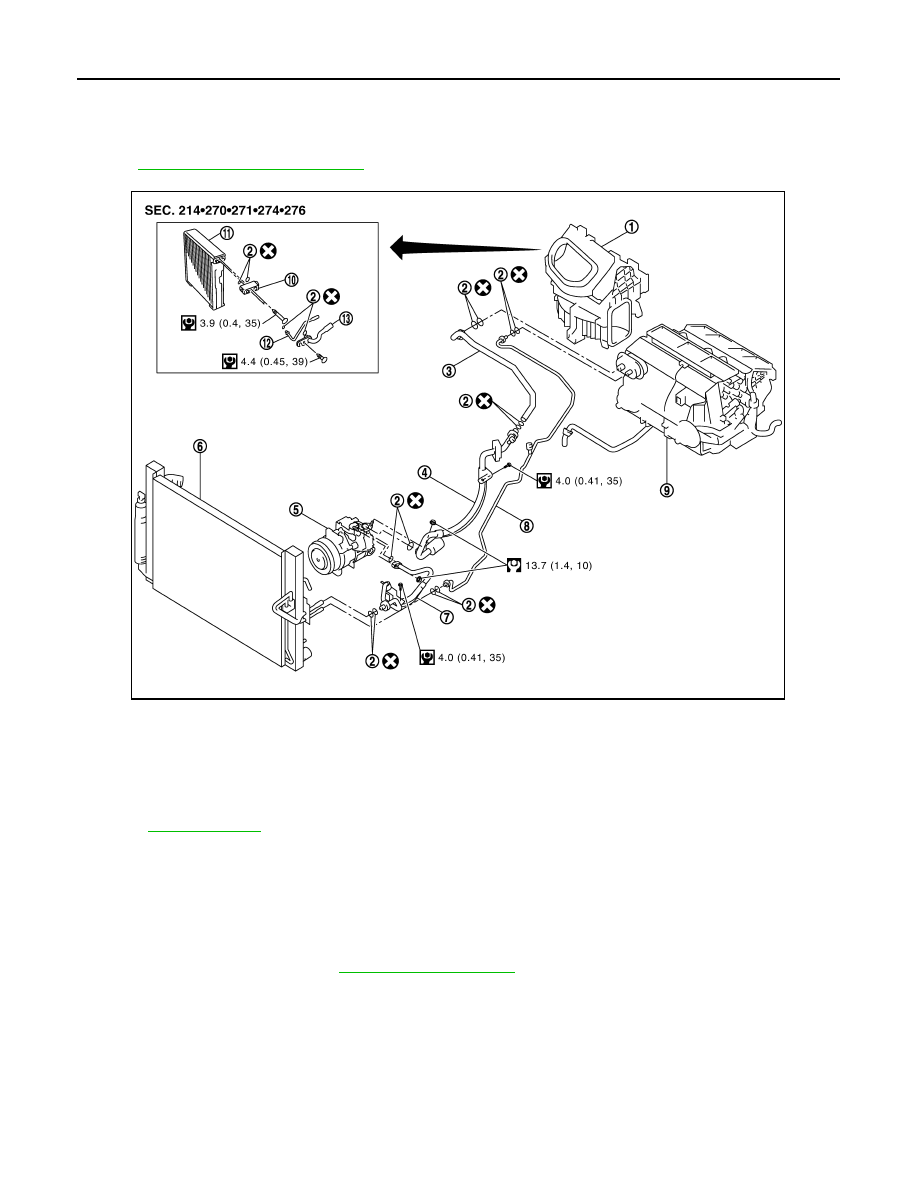
Exploded View
INFOID:0000000001713750
HA-13, "Refrigerant Connection"
.
Removal and Installation
INFOID:0000000001675644
REMOVAL
1.
Set the temperature at 18
°
C (60
°
F). Then disconnect the battery cable from the negative terminal.
2.
Use a refrigerant collecting equipment (for HFC-134a) to discharge the refrigerant.
3.
Remove cowl top cover. Refer to
.
1.
Blower unit
2.
O-ring
3.
Low-pressure pipe 2
4.
Low-pressure flexible hose
5.
Compressor
6.
Radiator & condenser assembly
7.
High-pressure flexible hose
8.
High-pressure pipe 1
9.
Heater & cooling unit assembly
10. Expansion valve
11.
Evaporator
12. High-pressure pipe 2
13. Low-pressure pipe 1
Refer to
for symbols in the figure.
JSIIA0109GB