Infiniti G37 Coupe. Manual - part 688
EXL-172
< ECU DIAGNOSIS >
[XENON TYPE]
AFS CONTROL UNIT
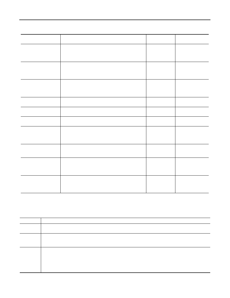
Fail Safe
INFOID:0000000001607804
DTC Inspection Priority Chart
INFOID:0000000001607805
If some DTCs are displayed at the same time, perform inspections one by one based on the following priority
chart.
DTC
Fail-safe
AFS OFF indica-
tor lamp
Cancellation
CAN COMM CIRCUIT
[U1000]
• Right and left swivel motors stop at the position when
DTC is detected.
• Right and left aiming motors stop at the position when
DTC is detected.
Blinks 1 second
each.
The ignition switch
OFF
CONTROL UNIT (CAN)
[U1010]
• Right and left swivel motors stop at the position when
DTC is detected.
• Right and left aiming motors stop at the position when
DTC is detected.
Blinks 1 second
each.
The ignition switch
OFF
SWIVEL ACTUATOR
[RH, LH]
[B2503, B2504]
• Right and left swivel motors stop at the position when
DTC is detected.
• The signal, approximately 2 V decreased from the level-
izer signal when DTC detected, is output.
Blinks 1 second
each.
The ignition switch
OFF
HI SEN UNUSUAL [RR]
[B2514]
• Right and left aiming motors stop at the position when
DTC is detected.
—
The ignition switch
OFF
ST ANG SEN SIG
[C0126]
• Right and left swivel motor swivel angle returns to 0
°
and
fixed.
Blinks 1 second
each.
The ignition switch
OFF
SHIFT SIG [P, R]
[B2516]
• Right and left swivel motor swivel angle returns to 0
°
and
fixed.
Blinks 1 second
each.
The ignition switch
OFF
VEHICLE SPEED SIG
[B2517]
• Right and left swivel motor swivel angle returns to 0
°
and
fixed.
• Right and left aiming motors stop at the position when
DTC is detected.
Blinks 1 second
each.
The ignition switch
OFF
LEVELIZER CALIB
[B2519]
• Right and left aiming motors stop at the position when
DTC is detected.
—
When the levelizer
adjustment is com-
pleted.
ST ANGLE SEN CALIB
[C0428]
• Right and left swivel motor swivel angle returns to 0
°
and
fixed.
Blinks 1 second
each.
When the steering
angle sensor neutral
position registration is
competed
ECU CIRC
[B2521]
• Right and left swivel motors stop at the position when
DTC is detected.
• Right and left aiming motors stop at the position when
DTC is detected.
Blinks 1 second
each.
The ignition switch
OFF
Priority
Detected items (DTC)
1
• U1000 CAN COMM CIRCUIT
• U1010 CONTROL UNIT (CAN)
2
• B2519 LEVELIZER CALIB
• B2521 ECU CIRC
• C0428 ST ANG SEN CALIB
3
• B2503 SWIVEL ACTUATOR [RH]
• B2504 SWIVEL ACTUATOR [LH]
• B2514 HI SEN UNUSUAL [RR]
• B2516 SHIFT SIG [P, R]
• B2517 VEHICLE SPEED SIG
• C0126 ST ANG SEN SIG