Infiniti G37 Coupe. Manual - part 629


  Index      Infiniti     Infiniti G37 Coupe - service repair manual 2008 year


Search            


Content   ..  627  628  629  630   ..


Infiniti G37 Coupe. Manual - part 629


CAMSHAFT

EM-91

< DISASSEMBLY AND ASSEMBLY >

C

D

E

F

G

H

I

J

K

L

M

A

EM

N

P

O

c.

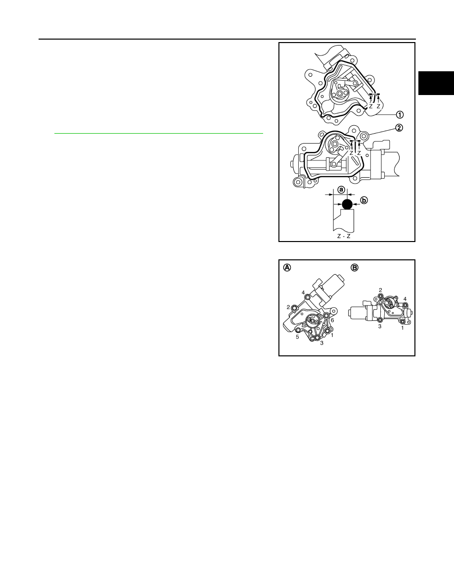
Apply a continuous bead of liquid gasket with tube presser
(commercial service tool) to the VVEL actuator sub assembly as
shown in the figure.

Use Genuine RTV Silicone Sealant or equivalent. Refer to

GI-15, "Recommended Chemical Products and Sealants"

.

CAUTION:

Never apply gasket to the oil passage.

d.

Install new VVEL actuator sub assembly.
• Tighten mounting bolts in the following step, in numerical order

as shown.

CAUTION:

• When installing, be careful with VVEL actuator sub

assembly (bank 2) mounting bolt No. 1 because its length
is different. 

• Be sure to check that the VVEL actuator sub assembly is

in contact with the cylinder head before tightening the
mounting bolts.

e.

Remove holding jig.

f.

Check that VVEL actuator arm bolt hole is aligned with control shaft tapped hole. If it is not aligned, turn
control shaft for alignment.

1

: VVEL actuator sub assembly (bank 2)

2

: VVEL actuator sub assembly (bank 1)

a

: 4.0 - 5.6 mm (0.157 - 0.220 in)

b

: 3.4 - 4.4 mm (0.134 - 0.173 in) dia.

JPBIA1125ZZ

A

:  Bank  2

B

:  Bank  1

JPBIA1114ZZ

EM-92

< DISASSEMBLY AND ASSEMBLY >

CAMSHAFT

g.

Fix two flat areas (C) of control shaft with a wrench to install
mounting bolts of control shaft.

CAUTION:

• During the operation, never allow a wrench to interfere

with other parts.

• Fix control shaft to prevent the interference of the stopper

surface.

11. Install new VVEL control shaft position sensor as follows:

CAUTION:

Regarding replacement, because VVEL actuator sub assembly and VVEL control shaft position
sensor are controlled on a one-on-one basis, replace them as a set.

a.

Apply engine oil to O-ring or contact surface of O-ring.

b.

Align matching marks (B) of VVEL control shaft position sensor
and upper housing.
• Face connector toward matching mark (A).

c.

Temporarily tighten bolt.

d.

Adjust VVEL control shaft position sensor after setting the engine assembly in the vehicle. Refer to 

EC-21,

"VVEL CONTROL SHAFT POSITION SENSOR ADJUSTMENT : Description"

.

CAUTION:

Be sure to adjust VVEL control shaft position sensor.

e.

After adjusting VVEL control shaft position sensor, tighten bolts to the specified torque. 

A

:  Bank  1

B

:  Bank  2

: Engine front

JPBIA1331ZZ

C

:  Bank  2

JPBIA1124ZZ

CAMSHAFT

EM-93

< DISASSEMBLY AND ASSEMBLY >

C

D

E

F

G

H

I

J

K

L

M

A

EM

N

P

O

12. Inspect the valve clearance. Refer to 

EM-17, "Inspection and Adjustment"

.

13. Install in the reverse order of removal after this step.

Inspection

INFOID:0000000001547605

INSPECTION AFTER REMOVAL (EXHAUST SIDE)

Camshaft (EXH) Runout

1.

Put V-block on precise flat table, and support No. 2 and 4 jour-
nals of camshaft.

CAUTION:

Never support No. 1 journal (on the side of camshaft
sprocket) because it has a different diameter from the other
three locations.

2.

Set a dial indicator vertically to No. 3 journal.

3.

Turn camshaft (EXH) to one direction with hands, and measure
the camshaft runout on a dial indicator. (Total indicator reading)

4.

If it exceeds the limit, replace camshaft (EXH).

Camshaft (EXH) Cam Height

• Measure the camshaft (EXH) cam height with a micrometer.

• If wear exceeds the limit, replace camshaft (EXH).

Camshaft (EXH) Journal Oil Clearance

CAMSHAFT (EXH) JOURNAL DIAMETER

• Measure the outer diameter of camshaft (EXH) journal with a

micrometer (A).

VVEL LADDER ASSEMBLY (EXH SIDE) INNER DIAMETER

• Tighten VVEL ladder assembly bolts to the specified torque. Refer to “INSTALLATION” for the tightening

procedure.

Standard and limit

: Refer to 

EM-139, "Camshaft"

.

PBIC0929E

Standard

Refer to 

EM-139, "Camshaft"

.

EMQ0072D

Standard

: Refer to 

EM-139, "Camshaft"

.

JPBIA0122ZZ

EM-94

< DISASSEMBLY AND ASSEMBLY >

CAMSHAFT

• Measure inner diameter (A) of VVEL ladder assembly (EXH side)

with a bore gauge.

CAMSHAFT (EXH) JOURNAL OIL CLEARANCE

• (Oil clearance) = [VVEL ladder assembly (EXH side) inner diameter] – [Camshaft (EXH) journal diameter].

• If the calculated value exceeds the limit, replace either or both camshaft (EXH) and VVEL ladder assembly &

cylinder head assembly.
NOTE:
VVEL ladder assembly cannot be replaced as a single part, because it is machined together with cylinder
head assembly.

Camshaft (EXH) End Play

• Install a dial indicator in thrust direction on front end of camshaft.

Measure the end play of a dial indicator when camshaft (EXH) is
moved forward/backward (in direction of axis).

• Measure the following parts if out of the limit.
- Dimension “A” for camshaft (EXH) No. 1 journal

- Dimension “B” for cylinder head No. 1 journal bearing

• Refer to the standards above, and then replace camshaft (EXH)

and/or VVEL ladder assembly & cylinder head assembly.
NOTE:
Cylinder head assembly cannot be replaced as a single part,
because it is machined together with VVEL ladder assembly.

Camshaft Sprocket (EXH) Runout

1.

Put V-block on precise flat table, and support No. 2 and 4 journals of camshaft (EXH).

CAUTION:

Never support No. 1 journal (on the side of camshaft sprocket) because it has a different diameter
from the other three locations.

Standard

: Refer to 

EM-139, "Camshaft"

.

PBIC1645E

Standard and limit

Refer to 

EM-139, "Camshaft"

.

Standard and limit

: Refer to 

EM-139, "Camshaft"

.

SEM864E

Standard

: 27.500 - 27.548 mm (1.0827 - 1.0846 in)

Standard

: 27.360 - 27.385 mm (1.0772 - 1.0781 in)

KBIA2404J


Content   ..  627  628  629  630   ..