Infiniti G37 Coupe. Manual - part 571


  Index      Infiniti     Infiniti G37 Coupe - service repair manual 2008 year


Search            


Content   ..  569  570  571  572   ..


Infiniti G37 Coupe. Manual - part 571


P2127, P2128 APP SENSOR

EC-465

< COMPONENT DIAGNOSIS >

[VQ37VHR]

C

D

E

F

G

H

I

J

K

L

M

A

EC

N

P

O

12.

REPLACE ACCELERATOR PEDAL ASSEMBLY

1.

Replace accelerator pedal assembly.

2.

Go to 

EC-465, "Special Repair Requirement"

.

>> INSPECTION END

13.

CHECK INTERMITTENT INCIDENT

Refer to 

GI-38, "Intermittent Incident"

.

>> INSPECTION END

Component Inspection

INFOID:0000000001911132

1.

CHECK ACCELERATOR PEDAL POSITION SENSOR

1.

Turn ignition switch OFF.

2.

Reconnect all harness connectors disconnected.

3.

Turn ignition switch ON.

4.

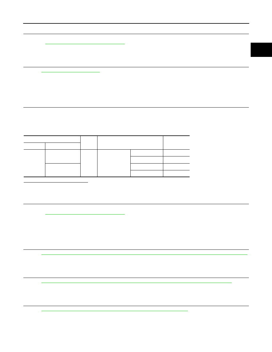
Check the voltage ECM harness connector and ground.

Is the inspection result normal?

YES

>> INSPECTION END

NO

>> GO TO 2.

2.

REPLACE ACCELERATOR PEDAL ASSEMBLY

1.

Replace accelerator pedal assembly.

2.

Go to 

EC-470, "Special Repair Requirement"

.

>> INSPECTION END

Special Repair Requirement

INFOID:0000000001911133

1.

PERFORM ACCELERATOR PEDAL RELEASED POSITION LEARNING

Refer to 

EC-18, "ACCELERATOR PEDAL RELEASED POSITION LEARNING : Special Repair Requirement"

.

>> GO TO 2.

2.

PERFORM THROTTLE VALVE CLOSED POSITION LEARNING

Refer to 

EC-18, "THROTTLE VALVE CLOSED POSITION LEARNING : Special Repair Requirement"

.

>> GO TO 3.

3.

PERFORM IDLE AIR VOLUME LEARNING

Refer to 

EC-19, "IDLE AIR VOLUME LEARNING : Special Repair Requirement"

.

>> END

ECM

Ground

Condition

Voltage

Connector

Terminal

M107

97 (APP sensor 1)

Ground

Accelerator pedal

Fully released

0.45 - 1.00V

Fully depressed

4.4 - 4.8V

98 (APP sensor 2)

Fully released

0.22 - 0.50V

Fully depressed

2.1 - 2.5V

EC-466

< COMPONENT DIAGNOSIS >

[VQ37VHR]

P2138 APP SENSOR

P2138 APP SENSOR

Description

INFOID:0000000001911131

The accelerator pedal position sensor is installed on the upper end
of the accelerator pedal assembly. The sensor detects the accelera-
tor position and sends a signal to the ECM.
Accelerator pedal position sensor has two sensors. These sensors
are a kind of potentiometers which transform the accelerator pedal
position into output voltage, and emit the voltage signal to the ECM.
In addition, these sensors detect the opening and closing speed of
the accelerator pedal and feed the voltage signals to the ECM. The
ECM judges the current opening angle of the accelerator pedal from
these signals and controls the throttle control motor based on these
signals.
Idle position of the accelerator pedal is determined by the ECM
receiving the signal from the accelerator pedal position sensor. The ECM uses this signal for the engine oper-
ation such as fuel cut.

DTC Logic

INFOID:0000000001734290

DTC DETECTION LOGIC

NOTE:
If DTC P2138 is displayed with DTC P0643, first perform the trouble diagnosis for DTC P0643. Refer to

EC-358, "DTC Logic"

.

DTC CONFIRMATION PROCEDURE

1.

PRECONDITIONING

If DTC Confirmation Procedure has been previously conducted, always perform the following before conduct-
ing the next test. 
1.

Turn ignition switch OFF and wait at least 10 seconds.

2.

Turn ignition switch ON.

3.

Turn ignition switch OFF and wait at least 10 seconds.

TESTING CONDITION:
Before performing the following procedure, confirm that battery voltage is more than 10V at idle.

>> GO TO 2.

2.

PERFORM DTC CONFIRMATION PROCEDURE

1.

Start engine and let it idle for 1 second.

2.

Check DTC.

Is DTC detected?

PBIB1741E

DTC No.

Trouble diagnosis name

DTC detecting condition

Possible cause

P2138

Accelerator pedal posi-
tion sensor circuit range/
performance

Rationally incorrect voltage is sent to ECM 
compared with the signals from APP sensor 1 
and APP sensor 2.

• Harness or connectors

(APP sensor 2 circuit is open or shorted.)
[CKP sensor (POS) circuit is shorted.]
(EVAP control system pressure sensor 
circuit is shorted.)
(Refrigerant pressure sensor circuit is 
shorted.)

• Accelerator pedal position sensor (APP 

sensor 2)
(Brake booster pressure sensor circuit is 
shorted)

• Crankshaft position sensor (POS)
• EVAP control system pressure sensor
• Brake booster pressure sensor
• Refrigerant pressure sensor

P2138 APP SENSOR

EC-467

< COMPONENT DIAGNOSIS >

[VQ37VHR]

C

D

E

F

G

H

I

J

K

L

M

A

EC

N

P

O

YES

>> Go to 

EC-467, "Diagnosis Procedure"

.

NO

>> INSPECTION END

Diagnosis Procedure

INFOID:0000000001734291

1.

CHECK GROUND CONNECTION

1.

Turn ignition switch OFF.

2.

Check ground connection M95. Refer to Ground Inspection in 

GI-41, "Circuit Inspection"

.

Is the inspection result normal?

YES

>> GO TO 2.

NO

>> Repair or replace ground connection.

2.

CHECK APP SENSOR 1 POWER SUPPLY CIRCUIT

1.

Disconnect accelerator pedal position (APP) sensor harness connector.

2.

Turn ignition switch ON.

3.

Check the voltage between APP sensor harness connector and ground.

Is the inspection result normal?

YES

>> GO TO 4.

NO

>> GO TO 3.

3.

DETECT MALFUNCTIONING PART

Check the following.
• Harness connectors M6, E106
• Harness for open or short between ECM and accelerator pedal position sensor

>> Repair open circuit or short to ground or short to power in harness or connectors.

4.

CHECK APP SENSOR 2 POWER SUPPLY CIRCUIT-I

1.

Turn ignition switch ON.

2.

Check the voltage between APP sensor harness connector and ground.

Is the inspection result normal?

YES

>> GO TO 9.

NO

>> GO TO 5.

5.

CHECK APP SENSOR 2 POWER SUPPLY CIRCUIT-II

1.

Turn ignition switch OFF.

2.

Disconnect ECM harness connector.

3.

Check the continuity between APP sensor harness connector and ECM harness connector.

Is the inspection result normal?

YES

>> GO TO 7.

NO

>> GO TO 6.

APP sensor

Ground

Voltage

Connector

Terminal

E112

5

Ground

Approx. 5V

APP sensor

Ground

Voltage

Connector

Terminal

E112

6

Ground

Approx. 5V

APP sensor

ECM

Continuity

Connector

Terminal

Connector

Terminal

E112

6

M107

103

Existed

EC-468

< COMPONENT DIAGNOSIS >

[VQ37VHR]

P2138 APP SENSOR

6.

DETECT MALFUNCTIONING PART

Check the following.
• Harness connectors M6, E106
• Harness for open or short between ECM and accelerator pedal position sensor

>> Repair open circuit.

7.

CHECK APP SENSOR 2 POWER SUPPLY CIRCUIT-III

Check harness for short to power and short to ground, between the following terminals.

Is the inspection result normal?

YES

>> GO TO 8.

NO

>> Repair short to ground or short to power in harness or connectors.

8.

CHECK COMPONENTS

Check the following.
• Crankshaft position sensor (POS) (Refer to 

EC-267, "Component Inspection"

.)

• Brake booster pressure sensor (Refer to 

EC-352, "Component Inspection"

.)

• EVAP control system pressure sensor (Refer to 

EC-306, "Component Inspection"

.)

• Refrigerant pressure sensor (Refer to 

HAC-85, "Diagnosis Procedure"

.)

Is the inspection result normal?

YES

>> GO TO 15.

NO

>> Replace malfunctioning component.

9.

CHECK APP SENSOR GROUND CIRCUIT FOR OPEN AND SHORT

1.

Turn ignition switch OFF.

2.

Disconnect ECM harness connector.

3.

Check the continuity between APP sensor harness connector and ECM harness connector.

4.

Also check harness for short to ground and short to power.

Is the inspection result normal?

YES

>> GO TO 11.

NO

>> GO TO 10.

10.

DETECT MALFUNCTIONING PART

Check the following.
• Harness connectors M6, E106
• Harness for open or short between ECM and accelerator pedal position sensor

>> Repair open circuit or short to ground or short to power in harness or connectors.

11.

CHECK APP SENSOR INPUT SIGNAL CIRCUIT FOR OPEN AND SHORT

ECM

Sensor

Connector

Terminal

Name

Connector

Terminal

F101

45

Brake booster pressure sensor

E48

1

46

CKP sensor (POS)

F2

1

M107

103

APP sensor

E112

6

107

EVAP control system pressure sensor

B30

3

111

Refrigerant pressure sensor

E77

3

APP sensor

ECM

Continuity

Connector

Terminal

Connector

Terminal

E112

4

M107

100

Existed

2

104


Content   ..  569  570  571  572   ..