Infiniti G37 Coupe. Manual - part 507


  Index      Infiniti     Infiniti G37 Coupe - service repair manual 2008 year


Search            


Content   ..  505  506  507  508   ..


Infiniti G37 Coupe. Manual - part 507


P0133, P0153 A/F SENSOR 1

EC-209

< COMPONENT DIAGNOSIS >

[VQ37VHR]

C

D

E

F

G

H

I

J

K

L

M

A

EC

N

P

O

>> Repair or replace malfunctioning part.

7.

PERFORM DTC CONFIRMATION PROCEDURE

1.

Turn ignition switch OFF and wait at least 10 seconds.

2.

Turn ignition switch ON.

3.

Turn ignition switch OFF and wait at least 10 seconds.

4.

Start engine and keep the engine speed between 3,500 and 4,000 rpm for at least 1minute under no load.

5.

Let engine idle for 1 minute.

6.

Increase the engine speed up to about 3,600 rpm and keep it for 10 seconds.

7.

Fully release accelerator pedal and then let engine idle for about 1 minute.

8.

Check 1st trip DTC.

Is 1st trip DTC detected?

YES

>> Go to 

EC-209, "Diagnosis Procedure"

.

NO

>> INSPECTION END

Diagnosis Procedure

INFOID:0000000001734044

1.

CHECK GROUND CONNECTION

1.

Turn ignition switch OFF.

2.

Check ground connection M95. Refer to Ground Inspection in 

GI-41, "Circuit Inspection"

.

Is the inspection result normal?

YES

>> GO TO 2.

NO

>> Repair or replace ground connection.

2.

RETIGHTEN A/F SENSOR 1

Loosen and retighten the A/F sensor 1. Refer to 

EM-33, "Removal and Installation"

.

>> GO TO 3.

3.

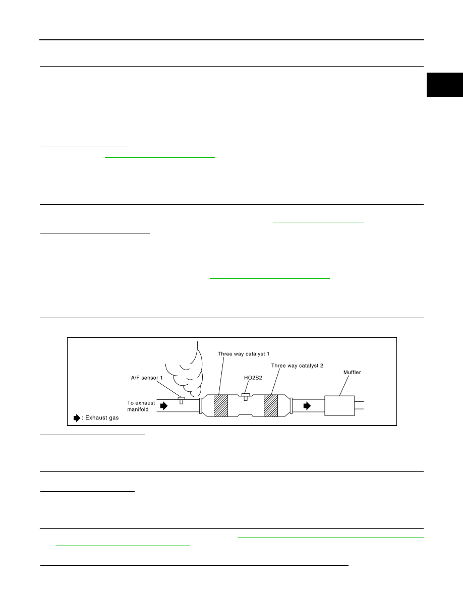
CHECK EXHAUST GAS LEAK

1.

Start engine and run it at idle.

2.

Listen for an exhaust gas leak before three way catalyst 1.

Is exhaust gas leak detected?

YES

>> Repair or replace.

NO

>> GO TO 4.

4.

CHECK FOR INTAKE AIR LEAK

Listen for an intake air leak after the mass air flow sensor.
Is intake air leak detected?

YES

>> Repair or replace.

NO

>> GO TO 5.

5.

CLEAR THE MIXTURE RATIO SELF-LEARNING VALUE

1.

Clear the mixture ratio self-learning value. Refer to 

EC-22, "MIXTURE RATIO SELF-LEARNING VALUE

CLEAR : Special Repair Requirement"

.

2.

Run engine for at least 10 minutes at idle speed.

Is the 1st trip DTC P0171, P172, P0174 or P0175 detected? Is it difficult to start engine?

PBIB1922E

EC-210

< COMPONENT DIAGNOSIS >

[VQ37VHR]

P0133, P0153 A/F SENSOR 1

YES

>> Perform trouble diagnosis for DTC P0171, P0174 or P0172, P0175. Refer to 

EC-232, "DTC Logic"

or 

EC-236, "DTC Logic"

.

NO

>> GO TO 6.

6.

CHECK AIR FUEL RATIO (A/F) SENSOR 1 POWER SUPPLY CIRCUIT

1.

Disconnect A/F sensor 1 harness connector.

2.

Turn ignition switch ON.

3.

Check the voltage between A/F sensor 1 harness connector and ground.

Is the inspection result normal?

YES

>> GO TO 8.

NO

>> GO TO 7.

7.

DETECT MALFUNCTIONING PART

Check the following.
• Harness connectors E3, F1
• IPDM E/R harness connector E7
• 15A fuse (No. 46)
• Harness for open or short between A/F sensor 1 and fuse

>> Repair or replace harness or connectors.

8.

CHECK A/F SENSOR 1 INPUT SIGNAL CIRCUIT FOR OPEN AND SHORT

1.

Turn ignition switch OFF.

2.

Disconnect ECM harness connector.

3.

Check the continuity between A/F sensor 1 harness connector and ECM harness connector.

4.

Check the continuity between A/F sensor 1 harness connector or ECM harness connector and ground.

5.

Also check harness for short to power.

Is the inspection result normal?

YES

>> GO TO 9.

NO

>> Repair open circuit or short to ground or short to power in harness or connectors.

9.

CHECK AIR FUEL RATIO (A/F) SENSOR 1 HEATER

Refer to 

EC-157, "Component Inspection"

.

DTC

A/F sensor 1

Ground

Voltage

Bank

Connector

Terminal

P0133

1

F3

4

Ground

Battery voltage

P0153

2

F20

4

DTC

A/F sensor 1

ECM

Continuity

Bank

Connector

Terminal

Connector

Terminal

P0133

1

F3

1

F102

57

Existed

2

61

P0153

2

F20

1

65

2

66

DTC

A/F sensor 1

ECM

Ground

Continuity

Bank

Connector

Terminal

Connector

Terminal

P0133

1

F3

1

F102

57

Ground

Not existed

2

61

P0153

2

F20

1

65

2

66

P0133, P0153 A/F SENSOR 1

EC-211

< COMPONENT DIAGNOSIS >

[VQ37VHR]

C

D

E

F

G

H

I

J

K

L

M

A

EC

N

P

O

Is the inspection result normal?

YES

>> GO TO 10.

NO

>> GO TO 13.

10.

CHECK MASS AIR FLOW SENSOR

Check both mass air flow sensor (bank 1 and bank 2).
Refer to 

EC-169, "Component Inspection"

.

Is the inspection result normal?

YES

>> GO TO 11. 

NO

>> Replace malfunctioning mass air flow sensor.

11.

CHECK PCV VALVE

Refer to 

EC-509, "Component Inspection"

.

Is the inspection result normal?

YES

>> GO TO 12.

NO

>> Repair or replace PCV valve.

12.

CHECK INTERMITTENT INCIDENT

Perfor

GI-38, "Intermittent Incident"

.

Is the inspection result normal?

YES

>> GO TO 13.

NO

>> Repair or replace.

13.

REPLACE AIR FUEL RATIO (A/F) SENSOR 1

Replace malfunctioning air fuel ratio (A/F) sensor 1.

CAUTION:

• Discard any A/F sensor which has been dropped from a height of more than 0.5 m (19.7 in) onto a

hard surface such as a concrete floor; use a new one.

• Before installing new A/F sensor, clean exhaust system threads using Oxygen Sensor Thread

Cleaner tool J-43897-18 or J-43897-12 and approved anti-seize lubricant.

>> INSPECTION END

EC-212

< COMPONENT DIAGNOSIS >

[VQ37VHR]

P0137, P0157 HO2S2

P0137, P0157 HO2S2

Description

INFOID:0000000001734045

The heated oxygen sensor 2, after three way catalyst 1, monitors the
oxygen level in the exhaust gas on each bank.
Even if switching characteristics of the air fuel ratio (A/F) sensor 1
are shifted, the air-fuel ratio is controlled to stoichiometric, by the sig-
nal from the heated oxygen sensor 2.
This sensor is made of ceramic zirconia. The zirconia generates volt-
age from approximately 1V in richer conditions to 0V in leaner condi-
tions.
Under normal conditions the heated oxygen sensor 2 is not used for
engine control operation.

DTC Logic

INFOID:0000000001734046

DTC DETECTION LOGIC

The heated oxygen sensor 2 has a much longer switching time
between rich and lean than the air fuel ratio (A/F) sensor 1. The oxy-
gen storage capacity of the three way catalyst 1 causes the longer
switching time. To judge the malfunctions of heated oxygen sensor
2, ECM monitors whether the maximum voltage of the sensor is suf-
ficiently high during the various driving condition such as fuel-cut.

DTC CONFIRMATION PROCEDURE

1.

INSPECTION START

Do you have CONSULT-III?

Do you have CONSULT-III?

YES

>> GO TO 2.

NO

>> GO TO 5.

2.

PRECONDITIONING

If DTC confirmation Procedure has been previously conducted, always perform the following before conduct-
ing the next test.
1.

Turn ignition switch OFF and wait at least 10 seconds.

2.

Turn ignition switch ON.

3.

Turn ignition switch OFF and wait at least 10 seconds.

TESTING CONDITION:
For better results, perform “DTC WORK SUPPORT” at a temperature of 0 to 30 

°

C (32 to 86 

°

F).

>> GO TO 3.

SEF327R

SEF259VA

DTC No.

Trouble diagnosis name

DTC detecting condition

Possible cause

P0137

Heated oxygen sensor 2 
(bank 1) circuit low volt-
age

The maximum voltage from the sensor is not 
reached to the specified voltage.

• Harness or connectors

(The sensor circuit is open or shorted)

• Heated oxygen sensor 2
• Fuel pressure
• Fuel injector
• Intake air leaks

P0157

Heated oxygen sensor 2 
(bank 2) circuit low volt-
age


Content   ..  505  506  507  508   ..