Infiniti G37 Coupe. Manual - part 479
INTAKE VALVE TIMING CONTROL
EC-97
< FUNCTION DIAGNOSIS >
[VQ37VHR]
C
D
E
F
G
H
I
J
K
L
M
A
EC
N
P
O
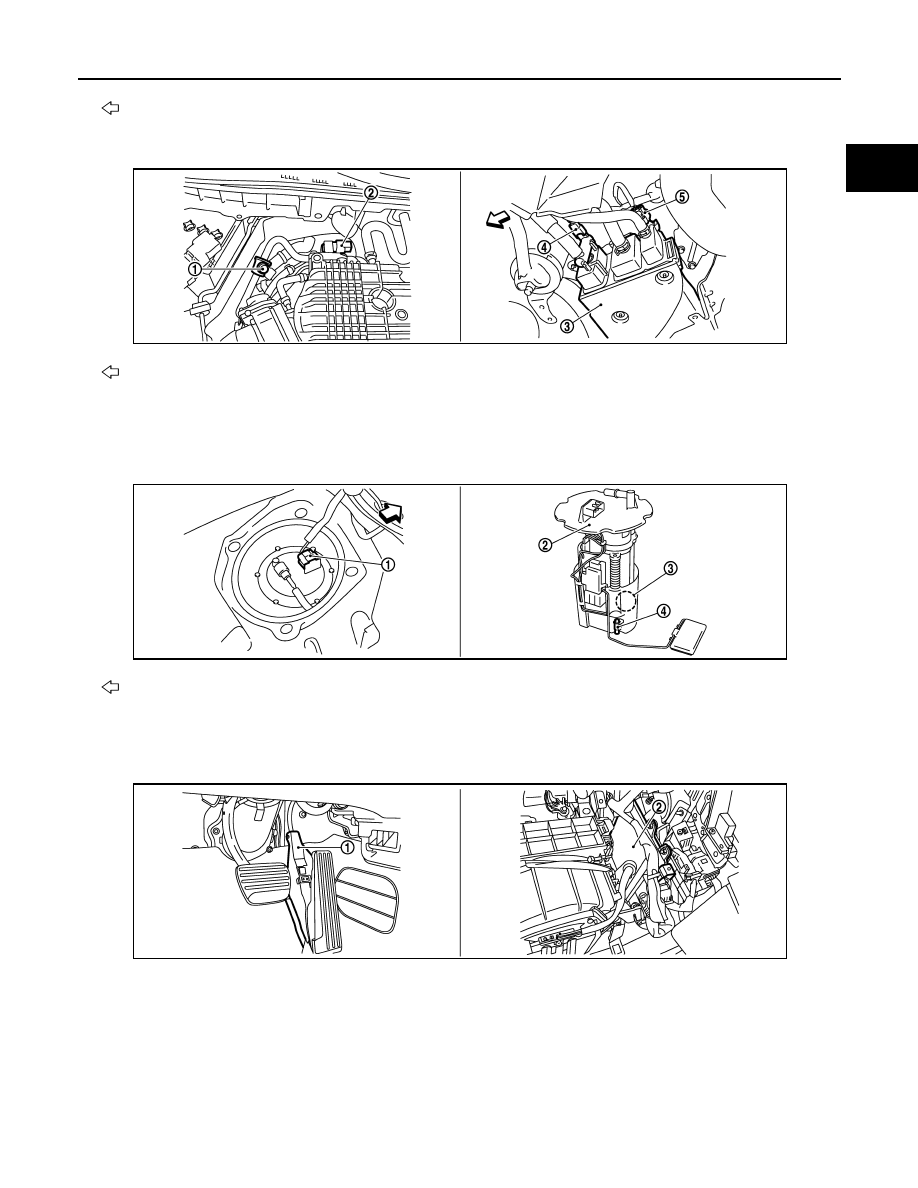
: Vehicle front
1.
Power steering pressure sensor
2.
Alternator
3.
Engine oil temperature sensor
: Vehicle front
1.
EVAP service port
2.
EVAP canister purge volume control
solenoid valve
3.
EVAP canister
4.
EVAP canister vent control valve
5.
EVAP control system pressure sen-
sor
: Vehicle front
1.
Fuel level sensor unit and fuel pump
harness connector
2.
Fuel level sensor unit and fuel pump 3.
Fuel pressure regulator
4.
Fuel tank temperature sensor
1.
Accelerator pedal position sensor
2.
ECM
JMBIA0845ZZ
JMBIA0019ZZ
JMBIA0015ZZ