Infiniti G37 Coupe. Manual - part 466
ELECTRIC IGNITION SYSTEM
EC-45
< FUNCTION DIAGNOSIS >
[VQ37VHR]
C
D
E
F
G
H
I
J
K
L
M
A
EC
N
P
O
ELECTRIC IGNITION SYSTEM
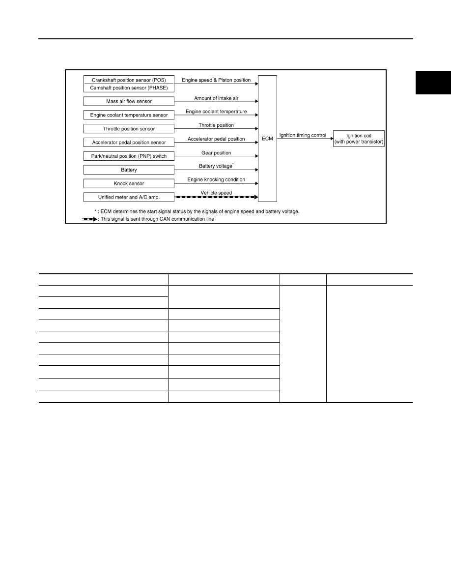
System Diagram
INFOID:0000000001733935
System Description
INFOID:0000000001733936
INPUT/OUTPUT SIGNAL CHART
*1: This signal is sent to the ECM through CAN communication line.
*2: ECM determines the start signal status by the signals of engine speed and battery voltage.
SYSTEM DESCRIPTION
Firing order: 1 - 2 - 3 - 4 - 5 - 6
The ignition timing is controlled by the ECM to maintain the best air-fuel ratio for every running condition of the
engine. The ignition timing data is stored in the ECM.
The ECM receives information such as the injection pulse width and camshaft position sensor (PHASE) sig-
nal. Computing this information, ignition signals are transmitted to the power transistor.
During the following conditions, the ignition timing is revised by the ECM according to the other data stored in
the ECM.
• At starting
• During warm-up
• At idle
• At low battery voltage
• During acceleration
The knock sensor retard system is designed only for emergencies. The basic ignition timing is programmed
within the anti-knocking zone, if recommended fuel is used under dry conditions. The retard system does not
JMBIA0072GB
Sensor
Input Signal to ECM
ECM function
Actuator
Crankshaft position sensor (POS)
Engine speed*
2
Piston position
Ignition timing
control
Ignition coil (with power tran-
sistor)
Camshaft position sensor (PHASE)
Mass air flow sensor
Amount of intake air
Engine coolant temperature sensor
Engine coolant temperature
Throttle position sensor
Throttle position
Accelerator pedal position sensor
Accelerator pedal position
Park/neutral position (PNP) switch
Gear position
Battery
Battery voltage*
2
Knock sensor
Engine knocking
Unified meter and A/C amp.
Vehicle speed*
1