Infiniti G37 Coupe. Manual - part 460
INSPECTION AND ADJUSTMENT
EC-21
< BASIC INSPECTION >
[VQ37VHR]
C
D
E
F
G
H
I
J
K
L
M
A
EC
N
P
O
VVEL CONTROL SHAFT POSITION SENSOR ADJUSTMENT : Description
INFOID:0000000001736789
VVEL control shaft position sensor adjustment is an operation to adjust the initial position angle that is the
basis for the VVEL control shaft position sensor.
It must be performed each time VVEL actuator sub assembly is replaced.
CAUTION:
• It must be performed only on the replaced bank side.
• It must not be performed except when VVEL actuator sub assembly is replaced. If by any chance the
adjustment is performed, replace VVEL actuator sub assembly.
VVEL CONTROL SHAFT POSITION SENSOR ADJUSTMENT : Special Repair Re-
quirement
INFOID:0000000001736790
1.
START
Do you have CONSULT-III?
Do you have CONSULT-III?
YES
>> GO TO 2.
NO
>> GO TO 3.
2.
PERFORM VVEL CONTROL SHAFT POSITION SENSOR ADJUSTMENT
With CONSULT-III
1.
Turn ignition switch ON.
2.
Select “VVEL POS SEN ADJ PREP” in “WORK SUPPORT” mode with CONSULT-III.
3.
Touch “Start” and wait a few seconds.
4.
Make sure the “CMPLT” is displayed on CONSULT-III screen.
5.
Select “VVEL POSITION SEN- B1” or “VVEL POSITION SEN- B2” in “DATA MONITOR” mode with CON-
SULT-III.
6.
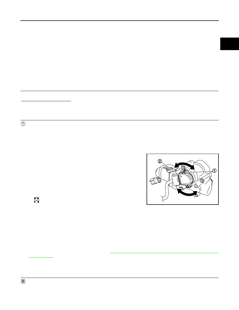
Loosen the VVEL control shaft position sensor mounting bolt (1).
7.
Turn the VVEL control shaft position sensor (2) right and left
while monitoring the output voltage of “VVEL POSITION SEN-
B1” or “VVEL POSITION SEN-B2” and adjust the output voltage
to be within the standard value.
8.
Tighten the VVEL control shaft position sensor mounting bolt.
9.
Reconfirm that the output voltage of “VVEL POSITION SEN- B1”
or “VVEL POSITION SEN- B2” is within the standard value.
NOTE:
If it varies from the standard value after the bolt is tightened, perform steps 6 to 8 again.
10. Turn ignition switch OFF and wait at least 10 seconds.
11. Start engine and warm it up to normal operating temperature.
12. Turn ignition switch OFF and wait at least 10 seconds.
13. Perform idle air volume learning. Refer to
EC-19, "IDLE AIR VOLUME LEARNING : Special Repair
.
>> INSPECTION END
3.
PERFORM VVEL CONTROL SHAFT POSITION SENSOR ADJUSTMENT
Without CONSULT-III
1.
Disconnect VVEL control shaft position sensor harness connector.
2.
Remove VVEL actuator motor relay.
3.
Turn ignition switch ON, wait at least 5 seconds and then turn OFF.
Voltage
: 500
±
48mV
: 7.0 N•m (0.71kg-m, 62in-lb)
Voltage
: 500
±
48mV
JMBIA0740ZZ