Infiniti G37 Coupe. Manual - part 450


  Index      Infiniti     Infiniti G37 Coupe - service repair manual 2008 year


Search            


Content   ..  448  449  450  451   ..


Infiniti G37 Coupe. Manual - part 450


DLN-114

< DISASSEMBLY AND ASSEMBLY >

[REAR FINAL DRIVE: R200V]

DIFFERENTIAL ASSEMBLY

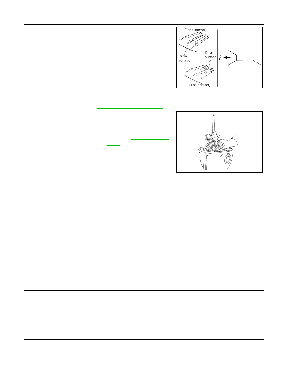
• If the tooth contact is near the flank (flank contact), or near the

toe (toe contact), thin pinion height adjusting washers to move
drive pinion farther from drive gear.

BACKLASH

• Before inspection and adjustment, drain gear oil.

1.

Remove rear cover. Refer to 

DLN-104, "A/T : Disassembly"

.

2.

Fit a dial indicator to the drive gear face to measure the back-
lash.

• If the backlash is outside of the specified value, change the

thickness of side bearing adjusting washer.

CAUTION:

Never change the total amount of washers as it changes the bearing preload.

A/T : Inspection After Disassembly

INFOID:0000000001714281

Clean up the disassembled parts. Then, inspect if the parts are worn or damaged. If so, follow the measures
below.

PDIA0441E

Standard

Backlash

: Refer to 

DLN-132, "Back-

lash"

.

When the backlash is large:

Make drive gear back side adjusting washer thicker, 
and drive gear tooth side adjusting washer thinner by 
the same amount.

When the backlash is small:

Make drive gear back side adjusting washer thinner, 
and drive gear tooth side adjusting washer thicker by 
the same amount.

SPD513

Content

Conditions and Measures

Hypoid gear

• If the gear teeth do not mesh or line-up correctly, determine the cause and adjust or replace as nec-

essary.

• If the gears are worn, cracked, damaged, pitted or chipped (by friction) noticeably, replace with new 

drive gear and drive pinion as a set.

Bearing

• If any chipped (by friction), pitted, worn, rusted or scratched mark, or unusual noise from the bearing 

is observed, replace as a bearing assembly (as a new set).

Side gear and pinion mate 
gear

• If any cracks or damage on the surface of the tooth is found, replace.
• If any worn or chipped mark on the contact sides of the thrust washer is found, replace.

Side gear thrust washer and 
pinion mate thrust washer

• If it is chipped (by friction), damaged, or unusually worn, replace.

Oil seal 

• Whenever disassembled, replace.
• If wear, deterioration of adherence (sealing force lips), or damage is detected on the lips, replace them.

Differential case

• If any wear or crack on the contact sides of the differential case is found, replace.

Companion flange

• If any chipped mark (about 0.1 mm, 0.004 in) or other damage on the contact sides of the lips of the 

companion flange is found, replace.

DRIVE PINION

DLN-115

< DISASSEMBLY AND ASSEMBLY >

[REAR FINAL DRIVE: R200V]

C

E

F

G

H

I

J

K

L

M

A

B

DLN

N

O

P

DRIVE PINION

M/T

M/T : Exploded View

INFOID:0000000001714282

1.

Drive pinion lock nut

2.

Companion flange

3.

Front oil seal

4.

Pinion front bearing

5.

Gear carrier

6.

Side oil seal

7.

Side flange

8.

Collapsible spacer

9.

Pinion rear bearing

10. Pinion height adjusting washer

11.

Drive pinion

12. Side bearing adjusting washer

13. Side bearing

14. Drive gear

15. Differential case B

16. Side gear thrust washer

17. Circular clip

18. Side gear

19. Pinion mate shaft

20. Pinion mate thrust washer

21. Pinion mate gear

22. Viscous coupling

23. Differential case A

24. Bearing cap

25. Filler plug

26. Gasket

27. Rear cover

28. Drain plug

A.

Oil seal lip

B.

Screw hole

C.

After tightening the bolts to the spec-
ified torque, tighten the bolts addi-
tionally by turning the bolts 31 to 36 
degrees.

:

Apply gear oil.

:

Apply anti-corrosion oil.

:

Apply Genuine Silicone RTV or equivalent. Refer to 

GI-15, "Recommended Chemical Products and Sealants"

.

JSDIA0037GB

DLN-116

< DISASSEMBLY AND ASSEMBLY >

[REAR FINAL DRIVE: R200V]

DRIVE PINION

M/T : Disassembly

INFOID:0000000001714283

1.

Remove differential case assembly. Refer to 

DLN-92, "M/T : Disassembly"

.

2.

Remove drive pinion lock nut with the flange wrench.

3.

Put matching mark (B) on the end of drive pinion. The matching
mark should be in line with the matching mark (A) on companion
flange (1).

CAUTION:

For matching mark, use paint. Never damage companion
flange and drive pinion.
NOTE:
The matching mark (A) on the final drive companion flange (1)
indicates the maximum vertical runout position.
When replacing companion flange, matching mark is not neces-
sary.

4.

Remove companion flange using the suitable pullers.

5.

Press drive pinion assembly out of gear carrier.

CAUTION:

Never drop drive pinion assembly.

6.

Remove front oil seal.

7.

Remove side oil seal.

8.

Remove pinion front bearing inner race.

9.

Remove collapsible spacer.

:

Apply Genuine High Strength Thread Locking Sealant or equivalent. Refer to 

GI-15, "Recommended Chemical Products 

and Sealants"

.

Refer to 

GI-4, "Components"

 for symbols not described on the above.

JSDIA0046ZZ

JSDIA0038ZZ

SDIA1132E

PDIA0760J

DRIVE PINION

DLN-117

< DISASSEMBLY AND ASSEMBLY >

[REAR FINAL DRIVE: R200V]

C

E

F

G

H

I

J

K

L

M

A

B

DLN

N

O

P

10. Remove pinion rear bearing inner race and pinion height adjust-

ing washer with the replacer (A).

11. Tap pinion front/rear bearing outer races uniformly using a brass

rod or equivalent to remove them.

CAUTION:

Never damage gear carrier.

M/T : Assembly

INFOID:0000000001714284

1.

Install front bearing outer race (1) and rear bearing outer race
(2) using drifts.

CAUTION:

• At first, using a hammer, tap bearing outer race until it

becomes flat to gear carrier.

• Never reuse pinion front and rear bearing outer race.

2.

Select drive pinion height adjusting washer. Refer to 

DLN-119,

"M/T : Adjustment"

.

PDIA0801J

SDIA0817E

A: Drift [SST: ST30720000 (J-25405)]

B: Drift [SST: KV40105230 (

)]

C: Drift bar [SST: ST30611000 (J-25742-1)]

D: Drift [SST: ST30613000 (J-25742-3)]

PDIA0761J


Content   ..  448  449  450  451   ..