Infiniti G37 Coupe. Manual - part 423


  Index      Infiniti     Infiniti G37 Coupe - service repair manual 2008 year


Search            


Content   ..  421  422  423  424   ..


Infiniti G37 Coupe. Manual - part 423


DLN-6

< ON-VEHICLE MAINTENANCE >

[REAR PROPELLER SHAFT: 3S80A]

REAR PROPELLER SHAFT

ON-VEHICLE MAINTENANCE

REAR PROPELLER SHAFT

Inspection

INFOID:0000000001714145

NOISE

• Check the propeller shaft tube surface for dents or cracks. If damaged, replace propeller shaft assembly.
• If center bearing is noisy or damaged, replace propeller shaft assembly.

VIBRATION

If vibration is present at high speed, inspect propeller shaft runout first.
1.

Measure propeller shaft runout at several points by rotating final
drive companion flange with hands.

2.

If runout still exceeds specifications, separate propeller shaft at
final drive companion flange; then rotate companion flange 90,
180, 270 degrees and install propeller shaft.

3.

Check runout again. If runout still exceeds specifications,
replace propeller shaft assembly. 

4.

Check the vibration by driving vehicle.

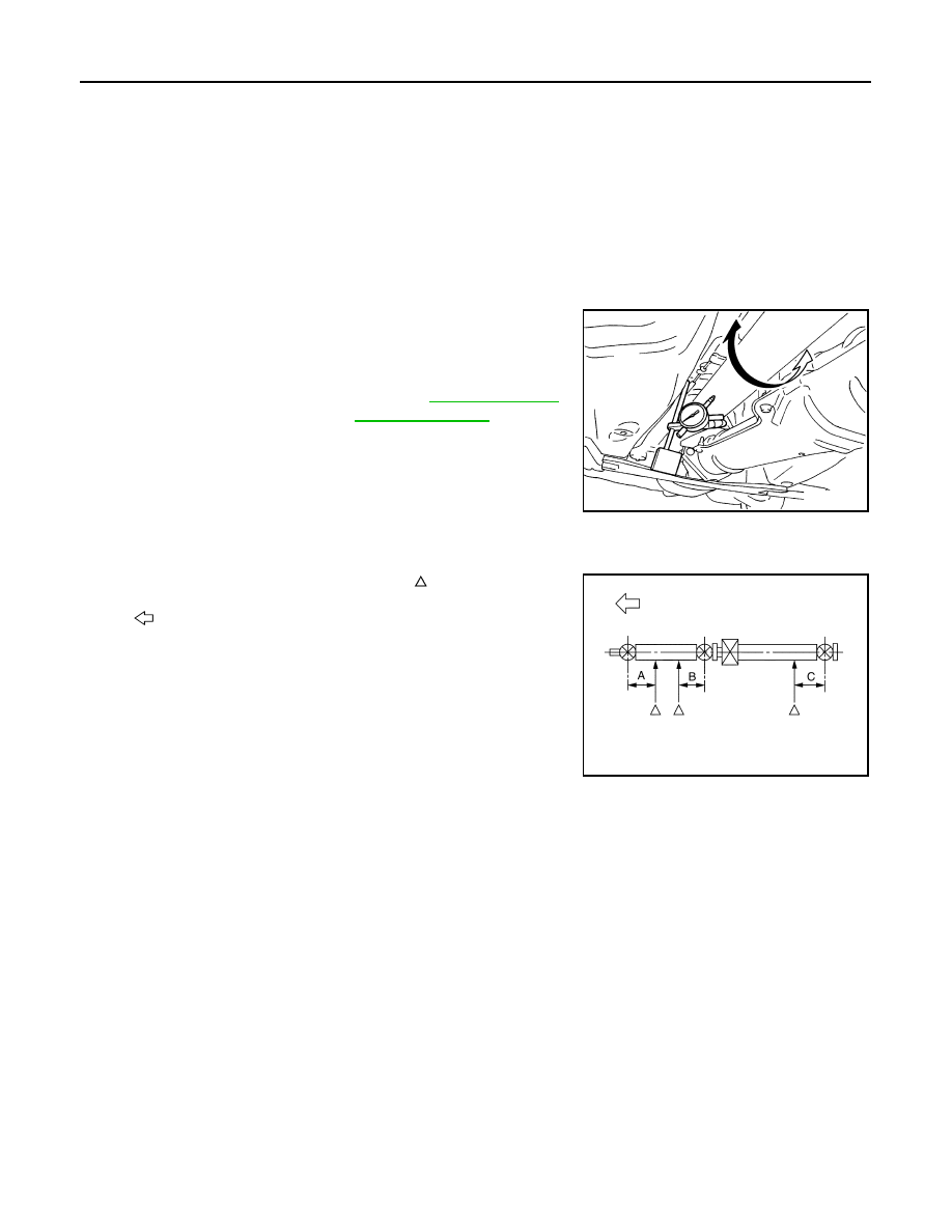
RUNOUT MEASURING POINT

Propeller shaft runout measuring point (Point “ ”).

Limit

Propeller shaft runout

: Refer to 

DLN-10, "Propel-

ler Shaft Runout"

.

SDIA1087E

: Vehicle front

Dimension

A: 192 mm (7.56 in)

B: 172 mm (6.77 in)

C: 170 mm (6.69 in)

PDIA0770J

REAR PROPELLER SHAFT

DLN-7

< ON-VEHICLE REPAIR >

[REAR PROPELLER SHAFT: 3S80A]

C

E

F

G

H

I

J

K

L

M

A

B

DLN

N

O

P

ON-VEHICLE REPAIR

REAR PROPELLER SHAFT

Exploded View

INFOID:0000000001714146

Removal and Installation

INFOID:0000000001714147

REMOVAL

1.

Move the M/T shift lever to neutral position and release the parking brake.

2.

Remove the floor reinforcement.

3.

Remove the center muffler with power tool. Refer to 

EX-5, "Exploded View"

.

4.

Remove the heat plate (1).

1.

Clip

2.

Center bearing mounting bracket 
(Upper)

3.

Propeller shaft assembly

4.

Center bearing mounting bracket 
(Lower)

: Vehicle front

Refer to 

GI-4, "Components"

 for symbols in the figure.

JSDIA0124GB

JSDIA0006ZZ

DLN-8

< ON-VEHICLE REPAIR >

[REAR PROPELLER SHAFT: 3S80A]

REAR PROPELLER SHAFT

5.

Put matching marks on propeller shaft flange yoke with final
drive companion flange.

CAUTION:

For matching marks, use paint. Never damage propeller
shaft flange yoke and final drive companion flange. 

6.

Loosen mounting nuts of center bearing mounting brackets.

CAUTION:

Tighten mounting nuts temporarily.

7.

Remove propeller shaft assembly fixing bolts and nuts.

8.

Remove center bearing mounting bracket fixing nuts.

9.

Remove propeller shaft assembly.

CAUTION:

• Never damage the rear oil seal of transmission. 
• If constant velocity joint was bent during propeller shaft

assembly removal, installation, or transportation, its boot
may be damaged. Wrap boot interference area to metal
part with shop cloth or rubber to protect boot from break-
age.

INSTALLATION

Note the following, and install in the reverse order of removal.
• Install center bearing mounting bracket (Upper) (1) with its arrow

mark (A) facing forward.

• Adjust position of center bearing mounting bracket (1, 2) sliding

back and forth to prevent play in thrust direction of center bearing
insulator (3). Install bracket to vehicle.

SDIA1822E

PDIA0402E

JSDIA0127ZZ

REAR PROPELLER SHAFT

DLN-9

< ON-VEHICLE REPAIR >

[REAR PROPELLER SHAFT: 3S80A]

C

E

F

G

H

I

J

K

L

M

A

B

DLN

N

O

P

• Align matching marks to install propeller shaft flange yoke with final

drive companion flange.

• After assembly, perform a driving test to check propeller shaft

vibration. If vibration occurred, separate propeller shaft from final
drive. Reinstall companion flange after rotating it by 90, 180, 270
degrees. Then perform driving test and check propeller shaft vibra-
tion again at each point.

• If propeller shaft or final drive has been replaced, connect them as

follows:

- Install the propeller shaft while aligning its matching mark (A) with

the matching mark (B) on the joint as close as possible.

CAUTION:

Never damage the rear oil seal of transmission. 

Inspection

INFOID:0000000001714148

APPEARANCE

• Check propeller shaft for bend and damage. If damage is detected, replace propeller shaft assembly.

PROPELLER SHAFT RUNOUT

• Check propeller shaft runout at measuring points. If runout

exceeds specifications, replace propeller shaft assembly. For mea-
suring point, refer to 

DLN-6, "Inspection"

.

JOURNAL AXIAL PLAY

• As shown in the figure, while fixing yoke on one side, check axial

play of joint. If outside the standard, replace propeller shaft assem-
bly. 

CAUTION:

Never disassemble joints.

CENTER BEARING

• Check center bearing for noise and damage. If noise or damage is detected, replace propeller shaft assem-

bly.

CAUTION:

Never disassemble center bearing.

SDIA1822E

PDIA0423E

Limit

Propeller shaft runout

: Refer to 

DLN-10, "Propel-

ler Shaft Runout"

.

JSDIA0111ZZ

Standard

Journal axial play 

: Refer to 

DLN-10, "Journal 

Axial Play"

.

PDA0005D


Content   ..  421  422  423  424   ..