Infiniti G37 Coupe. Manual - part 414
FRONT FENDER
DLK-217
< ON-VEHICLE REPAIR >
[INTELLIGENT KEY SYSTEM]
C
D
E
F
G
H
I
J
L
M
A
B
DLK
N
O
P
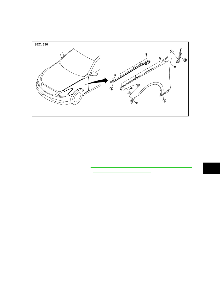
FRONT FENDER
Exploded View
INFOID:0000000001722594
Removal and Installation
INFOID:0000000001722595
REMOVAL
1.
Remove the front bumper fascia. Refer to
EXT-13, "Removal and Installation"
.
2.
Remove the hood seal assembly (side).
3.
Remove the front combination lamp. Refer to
EXL-189, "Removal and Installation"
.
4.
Remove the fender protector. Refer to
EXT-24, "FENDER PROTECTOR : Removal and Installation"
.
5.
Remove the center mudguard. Refer to
EXT-27, "Removal and Installation"
6.
Remove the mounting bolt and remove the front fender.
CAUTION:
While removing use a shop cloth to protect body from damaging.
INSTALLATION
Install in the reverse order of removal.
CAUTION:
• After installing, apply touch-up paint (the body color) onto the head of the front fender mounting
bolts.
• After installing, check front fender adjustment. Refer to
DLK-210, "HOOD ASSEMBLY : Adjustment"
DLK-219, "DOOR ASSEMBLY : Adjustment"
.
1.
Hood seal assembly (side)
2.
Front fender
3.
Baffle assembly
4.
Double-faced adhesive tape
JMKIA1215ZZ