Infiniti G37 Coupe. Manual - part 412


  Index      Infiniti     Infiniti G37 Coupe - service repair manual 2008 year


Search            


Content   ..  410  411  412  413   ..


Infiniti G37 Coupe. Manual - part 412


HOOD

DLK-209

< ON-VEHICLE REPAIR >

[INTELLIGENT KEY SYSTEM]

C

D

E

F

G

H

I

J

L

M

A

B

DLK

N

O

P

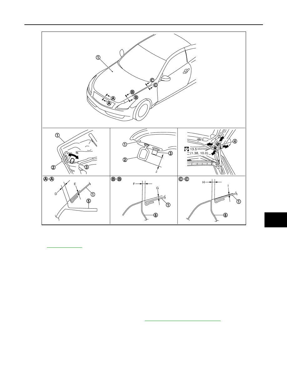
HOOD ASSEMBLY : Removal and Installation

INFOID:0000000001722587

CAUTION:

Operate with two workers, because of its heavy weight.

REMOVAL

1.

Support the hood lock assembly with a proper material to prevent it from falling.

WARNING:

Body injury may occur if no supporting rod is holding the hood open when removing the hood
stay.

2.

Remove the hood hinge cover (RH,LH).

3.

Remove the washer nozzle, washer tube. Refer to 

WW-86, "Removal and Installation"

.

4.

Remove the stud balls on the hood stays at the hood side.

5.

Remove the hinge mounting nuts on the hood to remove the hood assembly.

INSTALLATION

Install in the reverse order of removal.

CAUTION:

1.

Hood assembly

2.

Striker

3.

Hood bumper rubber

4.

Hood hinge

5.

Front bumper

6.

Front fender

Refer to 

GI-4, "Components"

 for symbols in the figure.

JMKIA1212GB

DLK-210

< ON-VEHICLE REPAIR >

[INTELLIGENT KEY SYSTEM]

HOOD

• Before installing hood hinge, apply anticorrosive agent onto the mounting surface of the vehicle

body.

• After installing, perform hood fitting adjustment. Refer to 

DLK-210, "HOOD ASSEMBLY : Adjust-

ment"

.

• After installing, perform front washer nozzle and tube inspection and adjustment. Refer to 

WW-86,

"Inspection and Adjustment"

.

HOOD ASSEMBLY : Adjustment

INFOID:0000000001722588

1.

Check the clearance and the surface height between the hood and each part visually and by touching.
(Fitting standard dimension in the table below should be satisfied.

2.

In case out of specification, adjust them according to the procedures shown below.

3.

Remove the striker and adjust the surface height of hood, front bumper and front fender according to the
fitting standard dimension, by rotating hood bumper rubbers. 

4.

Adjust the height difference of striker, hood bumper rubber according to the fitting standard dimension. 

5.

Loosen the hood hinge mounting nuts on the hood.

6.

Adjust the clearance of hood, front bumper and front fender according to the fitting standard dimension,
for the hood.

7.

Check that the hood lock primary latch is securely engaged with the striker by dropping hood from approx-
imately 200 mm (7.874 in) height or pressing lightly on the hood.

CAUTION:

Do not drop hood from a height of 300 mm (11.811 in) or more.

8.

Install as static closing face of hood is 94 – 490 N·m (9.6 – 50.0 kg-m).
NOTE:
• Exercise vertical force on right side and left side of hood lock.
• Do not press simultaneously both sides.

9.

After adjustment tighten hood hinge mounting nuts to the specified torque.

HOOD LOCK CONTROL

Portion

Standard

Right/left 

Clearance (MAX)

Hood – Front bumper

A – A

D

Clearance

2.0 – 5.0 mm

(0.079 – 0.197 in)

E

Surface height

1.0 – 2.0 mm

(

0.039 – 0.079 in)

Hood – Front fender

B – B

F

Clearance

2.5 – 4.5 mm 

(0.098 – 0.177 in)

2.0 mm (0.079 in)

G

Surface height

1.0 – 2.0 mm

(

0.039 – 0.079 in)

C – C

H

Clearance

2.5 – 4.5 mm

(0.098 – 0.177 in)

2.0 mm (0.079 in)

I

Surface height

1.0 – 1.0 mm

 (

0.039 – 0.039 in)

Striker – Hood bumper 
rubber

J

Height difference

32.5 – 33.5 mm

(1.280 – 1.319 in)

HOOD

DLK-211

< ON-VEHICLE REPAIR >

[INTELLIGENT KEY SYSTEM]

C

D

E

F

G

H

I

J

L

M

A

B

DLK

N

O

P

HOOD LOCK CONTROL : Exploded View

INFOID:0000000001722589

HOOD LOCK CONTROL : Removal and Installation

INFOID:0000000001722590

REMOVAL

1.

Remove the washer tank. Refer to 

WW-83, "Removal and Installation"

.

2.

Remove the radiator core support ornament.
• Remove the radiator core support ornament mounting bolts

and clips.

NOTE:
To remove the mounting bolts on both sides of radiator core sup-
port ornament, first remove the mounting bolts of front bumper
(shown by arrows in the figure) and pull up the bumper edge
slightly to get working clearance.

CAUTION:

Do not apply excessive force while pulling front bumper to
prevent front bumper and front fender from being damaged.

• Hold both sides of radiator core support ornament, pull it upwards and slide it rearwards of the vehicle.

1.

Hood lock cover

2.

Striker

3.

Hood lock (RH)

4.

Hood lock switch harness connector 5.

Hood lock control cable (Front)

6.

Secondary latch

7.

Hood lock (LH)

8.

Hood lock control cable protector 
cover

9.

Hood lock control cable protector

10. Hood lock control cable (Rear)

11.

Hood lock opener

: Clip

Refer to 

GI-4, "Components"

 for symbols in the figure.

JMKIA1213GB

JMKIA0140ZZ

DLK-212

< ON-VEHICLE REPAIR >

[INTELLIGENT KEY SYSTEM]

HOOD

• Disconnect the harness clip and hood lock control cable clip

on radiator core support.

3.

Remove the fender protector (LH). Refer to 

DLK-217, "Removal and Installation"

.

4.

Disconnect hood lock switch (RH side) harness connector.

5.

Remove the hood lock bracket mounting bolts, and remove the hood lock bracket assembly. Refer to

DLK-214, "Exploded View"

.

6.

Remove the hood lock mounting bolts, and disassemble the hood lock from the hood lock bracket.

7.

Disconnect the hood lock control cable from the hood lock and
clip it to the hood ledge.

8.

Remove the hood lock control cable protector (1) from the head-
lamp assembly (2).

9.

Remove the hood lock control cable cover from hood lock control cable protector.

10. Disconnect the hood lock control cable from hood lock control

cable protector.

11. Remove the mounting screws and then remove the hood lock opener.

12. Remove the grommet on the dashboard, and pull the hood lock control cable toward the passenger com-

partment.

: Clip

JMKIA0141ZZ

JMKIA0041ZZ

: Pawl

JMKIA0202ZZ

JMKIA0203ZZ


Content   ..  410  411  412  413   ..