Infiniti G37 Coupe. Manual - part 341
CO-14
< ON-VEHICLE REPAIR >
RADIATOR
ON-VEHICLE REPAIR
RADIATOR
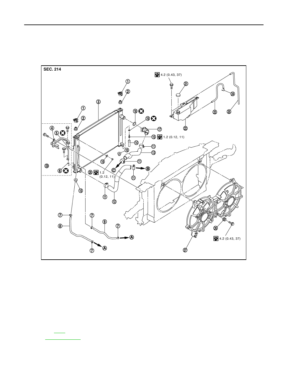
Exploded View
INFOID:0000000001547663
1.
Upper mount bracket
2.
Mounting rubber (upper)
3.
Radiator & condenser assembly
4.
Condenser pipe assembly
5.
O-ring
6.
O-ring
7.
Clamp
8.
A/T fluid cooler hose (A/T models)
9.
A/T fluid cooler hose (A/T models)
10. Mounting rubber (lower)
11.
Clamp
12. Radiator hose (lower)
13. Radiator hose (Upper)
14. Water drain hose
15. Drain plug
16. O-ring
17. Radiator water inlet pipe
18. O-ring
19. O-ring
20. Air relief plug
21. Reservoir tank cap
22. Reservoir tank
23. Reservoir tank hose
24. Clamp
25. Reservoir tank hose
26. Grommet
27. Radiator cooling fan assembly
A.
To transmission
B.
To water inlet
C.
To water outlet
D.
Refer to
for symbols in the figure.
JPBIA0246GB