Infiniti G37 Coupe. Manual - part 272
BRC-62
< COMPONENT DIAGNOSIS >
[VDC/TCS/ABS]
C1145, C1146 YAW RATE/SIDE G SENSOR
3.
Turn ignition switch ON or OFF and check voltage between yaw rate/side G sensor harness connector ter-
minal and ground.
Is the inspection result normal?
YES
>> GO TO 3.
NO
>> Repair or replace malfunctioning components.
3.
CHECK YAW RATE/SIDE G SENSOR GROUND CIRCUIT
Check continuity between yaw rate/side G sensor harness connector terminal and ground.
Is the inspection result normal?
YES
>> GO TO 4.
NO
>> Repair or replace malfunctioning components.
4.
CHECK YAW RATE/SIDE G SENSOR HARNESS
1.
Disconnect yaw rate/side G sensor connector and ABS actuator and electric unit (control unit) connector.
2.
Check continuity between yaw rate/side G sensor harness connector terminals and ABS actuator and
electric unit (control unit) harness connector terminals.
Is the inspection result normal?
YES
>> GO TO 5.
NO
>> Repair or replace malfunctioning components.
5.
CHECK DATA MONITOR
1.
Connect the yaw rate/side G sensor connector and ABS actuator and electric unit (control unit) connector.
2.
Select “YAW RATE SEN”, “SIDE G-SENSOR” in “DATA MONITOR” and check yaw rate/side G sensor
signal.
Is the inspection result normal?
YES
>> Replace ABS actuator and electric unit (control unit).
NO
>> Replace yaw rate/side G sensor.
Component Inspection
INFOID:0000000001635108
1.
CHECK DATA MONITOR
Select “YAW RATE SEN”, “SIDE G-SENSOR” in “DATA MONITOR” and check yaw rate/side G sensor signal.
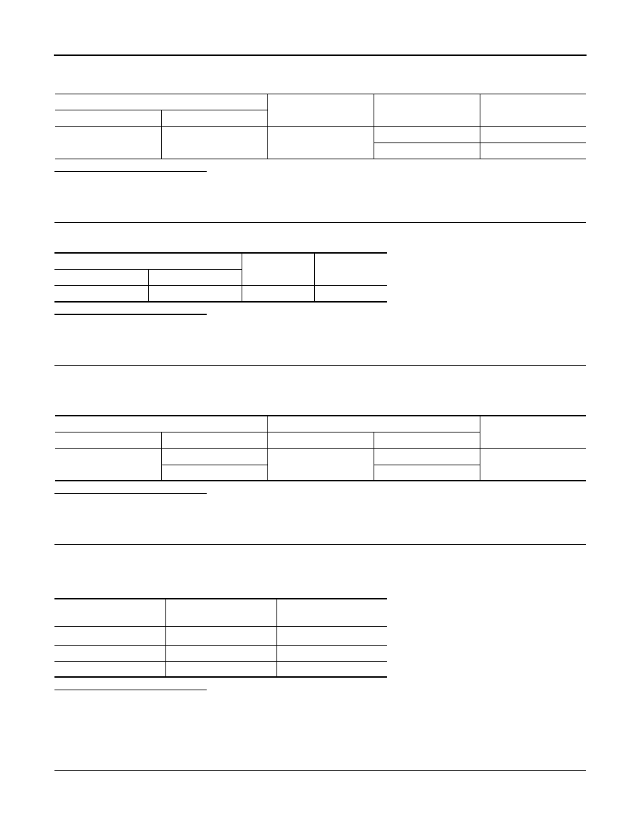
Yaw rate/side G sensor
—
Condition
Voltage
Connector
Terminal
M143
4
Ground
Ignition switch: ON
Battery voltage
Ignition switch: OFF
Approx. 0 V
Yaw rate/side G sensor
—
Continuity
Connector
Terminal
M143
1
Ground
Existed
ABS actuator and electric unit (control unit)
Yaw rate/side G sensor
Continuity
Connector
Terminal
Connector
Terminal
E41
25
M143
2
Existed
45
3
Vehicle condition
YAW RATE SEN
(DATA MONITOR)
SIDE G-SENSOR
(DATA MONITOR)
Vehicle stopped
Approx. 0 d/s
Approx. 0 m/s
2
Turning right
Negative value
Negative value
Turning left
Positive value
Positive value