Infiniti G37 Coupe. Manual - part 205
AV
IPOD ADAPTER
AV-573
< ECU DIAGNOSIS >
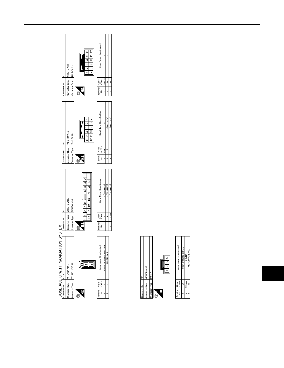
[BOSE AUDIO WITH NAVIGATION]
C
D
E
F
G
H
I
J
K
L
M
B
A
O
P
NOTE:
The name MULTIFUNCTION SWITCH indicates the integration of PRESET SWITCH and MULTIFUNCTION
SWITCH virtually.
JCNWA0498GB