Infiniti G37 Coupe. Manual - part 155


  Index      Infiniti     Infiniti G37 Coupe - service repair manual 2008 year


Search            


Content   ..  153  154  155  156   ..


Infiniti G37 Coupe. Manual - part 155


AV

MULTI AV SYSTEM

AV-373

< FUNCTION DIAGNOSIS >

[BOSE AUDIO WITH NAVIGATION]

C

D

E

F

G

H

I

J

K

L

M

B

A

O

P

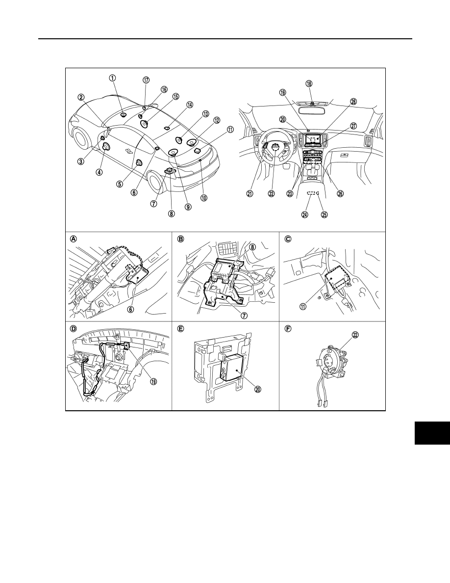
Component Parts Location

INFOID:0000000001558772

1.

Center speaker

2.

Tweeter LH

3.

Door squawker LH

4.

Door woofer LH

5.

Rear speaker LH

6.

Antenna amp.

7.

BOSE amp.

8.

Woofer amp.

9.

Rear woofer LH

10. Rear view camera

11. Camera control unit

12. Rear woofer RH

13. Rear speaker RH

14. Satellite radio antenna

15. Door woofer RH

16. Door squawker RH

17. Tweeter RH

18. Microphone

19. GPS antenna

20. iPod adapter

21. Steering switch

22. Steering angle sensor

23. Preset switch

24. Auxiliary input jacks

25. iPod connector

26. AV control unit

27. Multifunction switch

28. Display unit

A.

Within rear pillar finisher LH

B.

Trunk room LH

C.

Trunk room RH

D.

Instrument panel rear side

E.

Rear view of the display

F.

Spiral cable part

JPNIA0468ZZ

AV-374

< FUNCTION DIAGNOSIS >

[BOSE AUDIO WITH NAVIGATION]

MULTI AV SYSTEM

Component Description

INFOID:0000000001558773

Part name

Description

AV CONTROL UNIT

• Integrates hard disk drive (HDD) allowing map data and music data to be 

stored.

• It is the master unit of the MULTI AV system, and it is connected to each con-

trol unit by communication. It operates each system according to communi-
cation signals from the AV control unit.

• The AV control unit includes the audio, hands-free phone, voice control, nav-

igation, satellite radio, and vehicle information functions.

• It is connected to ECM and unified meter and A/C amp. via CAN communi-

cation to obtain necessary information for the vehicle information function.

• It is connected to BCM via CAN communication transmitting/receiving for the 

vehicle settings function.

• It inputs the illumination signals that are required for the display dimming con-

trol.

• It inputs the signals for driving status recognition (vehicle speed, reverse and 

parking brake). 

• Update of map data is performed with the CONSULT-III and the applicable 

cable.

DISPLAY UNIT

• Display image is controlled by the serial communication from AV control unit.
• RGB image signal is input from AV control unit (RGB, RGB area and RGB 

synchronizing). Auxiliary image signal is input from the auxiliary input jack. 
Camera image signal is input from camera control unit.

• Synchronize signal (HP, VP) is output to AV control unit.
• Touch panel function can be operated for each system by touching a display 

directly.

BOSE AMP.

Inputs power (amp ON) and sound signal from AV control unit, and outputs 
sound signal to woofer amp. and each speaker.

WOOFER AMP.

Inputs power (amp ON) and sound signal from BOSE amp., and outputs sound 
signal to each woofer.

DOOR WOOFER

• Outputs sound signal from BOSE amp.
• Outputs low-pitched sound.

DOOR SQUAWKER

• Outputs sound signal from BOSE amp.
• Outputs midrange sound.

REAR SPEAKER

• Outputs sound signal from BOSE amp.
• Outputs high, mid and low range sounds.

TWEETER

• Outputs sound signal from BOSE amp.
• Outputs high range sound.

CENTER SPEAKER

• Outputs sound signal from BOSE amp.
• Outputs high, mid and low range sounds.

REAR WOOFER

• Outputs sound signal from woofer amp.
• Outputs low-pitched sound.

MULTIFUNCTION SWITCH

• Operation panel is equipped with the centralized switch where audio, auxilia-

ry input and navigation operations are integrated.

• Connected with preset switch via cable, and operation signal is transmitted 

to AV control unit via AV communication. 

PRESET SWITCH

• Operation panel is equipped with the centralized switch where audio and air 

conditioner operations are integrated.

• Connected with multifunction switch via cable, and operation signal is trans-

mitted to AV control unit via AV communication.

• The CD ejection operating signal is performed by hardwire.

CAMERA CONTROL UNIT

• Camera image signal is input from rear view camera. Camera image signal 

output to display.

• Power (camera ON signal) is transmitted to rear view camera.
• Controlled by AV communication transmitted from AV control unit.
• AV control unit recognizes the presence of camera system with camera con-

nection recognition signal.

REAR VIEW CAMERA

The image of vehicle rear view is transmitted to camera control unit.

AV

MULTI AV SYSTEM

AV-375

< FUNCTION DIAGNOSIS >

[BOSE AUDIO WITH NAVIGATION]

C

D

E

F

G

H

I

J

K

L

M

B

A

O

P

STEERING SWITCH

• Operations for audio, hands-free phone, audio response and navigation, etc. 

are possible.

• Steering switch signal (operation signal) is output to AV control unit.

STEERING ANGLE SENSOR

Sensor signal (steering angle) is transmitted to camera control unit.

MICROPHONE

• Used for hands-free phone operation and voice recognition.
• Mic signal is transmitted to AV control unit.
• Power (Mic VCC) is supplied from AV control unit.

AUXILIARY INPUT JACKS

Image signal of auxiliary input is transmitted to display, and sound signal is 
transmitted to AV control unit.

GPS ANTENNA

GPS signal is received and transmitted to AV control unit.

ANTENNA AMP.

• Radio signal received by glass antenna is amplified and transmitted to AV 

control unit.

• Power (antenna amp ON signal) is supplied from AV control unit.

SATELLITE RADIO ANTENNA

Satellite radio signal is received and transmitted to AV control unit.

iPod ADAPTER

• Inputs iPod sound signal from iPod

®

, and outputs iPod sound signal to AV 

control unit.

• Receiving/transmitting of iPod

®

 operation signals are performed as follows:

- between AV control unit and iPod adapter: AV communication.

- between iPod

®

 and iPod adapter: serial communication.

Part name

Description

AV-376

< FUNCTION DIAGNOSIS >

[BOSE AUDIO WITH NAVIGATION]

NAVIGATION SYSTEM

NAVIGATION SYSTEM

System Diagram

INFOID:0000000001558774

System Description

INFOID:0000000001558775

DESCRIPTION

• The AV control unit controls navigation function while GPS tuner has built-in map data, GYRO (angle speed

sensor), on the HDD (Hard Disk Drive).

• The AV control unit inputs operation signal with communication signal, through display (touch panel) and

multifunction switch and steering switch.

• Guide sound is output to front speaker through BOSE amp. from AV control unit when operating navigation

system.

• A vehicle position is calculated with the GYRO (angle speed sensor), vehicle sensor, signal from GPS satel-

lite and map data stored on HDD (Hard Disk Drive), and transmits the map image signal (RGB image, RGB
area, RGB image synchronizing) to the display.

POSITION DETECTION PRINCIPLE

The navigation system periodically calculates the current vehicle
position according to the following three types of signals.
• Travel distance of the vehicle as determined by the vehicle speed

sensor

• Vehicle turning angle determined by the gyroscope (angular speed

sensor) 

• The travel direction of the vehicle determined by the GPS antenna

(GPS information)

The current position of the vehicle is then identified by comparing the
calculated vehicle position with map data, which is stored in the HDD
(Hard Disk Drive) (map-matching), and indicated on the screen with
a current location mark. More accurate data is used by comparing
position detection results from GPS to the map-matching.
The current position is calculated by detecting the travel distance
from the previous calculation point, and its direction change.
• Travel distance

The travel distance is generated from the vehicle speed sensor
input signal. The automatic distance correction function is adopted
for preventing a miss-detection of the travel distance because of
tire wear etc.

• Travel direction

The gyroscope (angular velocity sensor) and GPS antenna (GPS
information) generate the change of the travel direction. Both have
advantages and disadvantages as per the following descriptions.

JSNIA0054GB

JSNIA0177GB

SEL684V


Content   ..  153  154  155  156   ..