Content .. 1446 1447 1448 1449 ..
Infiniti G37 Coupe. Manual - part 1448
WW-66
< ECU DIAGNOSIS >
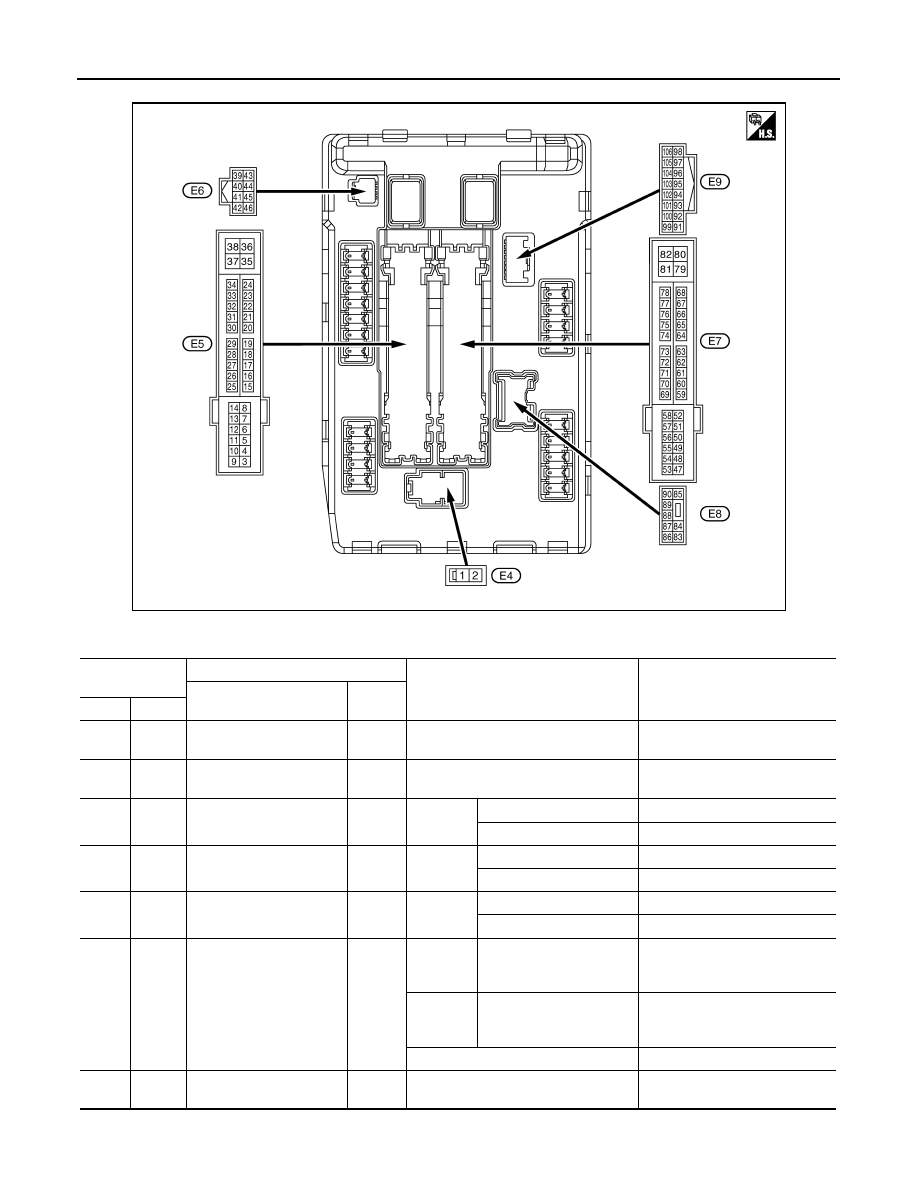
IPDM E/R (INTELLIGENT POWER DISTRIBUTION MODULE ENGINE ROOM)
TERMINAL LAYOUT
PHYSICAL VALUES
JSMIA0001ZZ
Terminal No.
(Wire color)
Description
Condition
Value
(Approx.)
Signal name
Input/
Output
+
−
1
(W)
Ground
Battery power supply
Input
Ignition switch OFF
Battery voltage
2
(L)
Ground
Battery power supply
Input
Ignition switch OFF
Battery voltage
4
(V)
Ground
Front wiper LO
Output
Ignition
switch ON
Front wiper switch OFF
0 V
Front wiper switch LO
Battery voltage
5
(L)
Ground
Front wiper HI
Output
Ignition
switch ON
Front wiper switch OFF
0 V
Front wiper switch HI
Battery voltage
7
(R)
Ground
Tail, license plate lamps &
illuminations
Output
Ignition
switch ON
Lighting switch OFF
0 V
Lighting switch 1ST
Battery voltage
11
(BR)
Ground
Steering lock unit power
supply
Output
Ignition
switch
OFF
A few seconds after open-
ing the driver door
Battery voltage
Ignition
switch
LOCK
Press the push-button ig-
nition switch
Battery voltage
Ignition switch ACC or ON
0 V
12
(B/W)
Ground
Ground
—
Ignition switch ON
0 V