Infiniti G37 Coupe. Manual - part 1430


  Index      Infiniti     Infiniti G37 Coupe - service repair manual 2008 year


Search            


Content   ..  1428  1429  1430  1431   ..


Infiniti G37 Coupe. Manual - part 1430


WT-92

< ON-VEHICLE MAINTENANCE >

ROAD WHEEL

ON-VEHICLE MAINTENANCE

ROAD WHEEL

Inspection

INFOID:0000000001687018

ALUMINUM WHEEL

1.

Check tires for wear and improper inflation.

2.

Check wheels for deformation, cracks and other damage. If deformed, remove wheel and check wheel
runout.

a.

Remove tire from aluminum wheel and mount on a tire balance machine.

b.

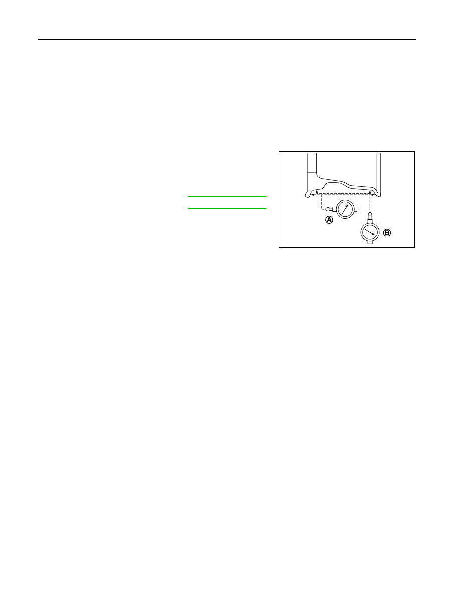
Set dial indicator as shown in the figure.

c.

If the total runout value exceeds the limit, replace aluminum
wheel.

Lateral runout limit (A)

Refer to 

WT-98, "Road Wheel"

.

Vertical runout limit (B)

Refer to 

WT-98, "Road Wheel"

.

SEIA0737E

ROAD WHEEL TIRE ASSEMBLY

WT-93

< ON-VEHICLE REPAIR >

C

D

F

G

H

I

J

K

L

M

A

B

WT

N

O

P

ON-VEHICLE REPAIR

ROAD WHEEL TIRE ASSEMBLY

Adjustment

INFOID:0000000001687019

BARANCING WHEELS (BONDING WEIGHT TYPE)

Preparation Before Adjustment

Using releasing agent, remove double-faced adhesive tape from the road wheel.

CAUTION:

• Be careful not scratch the road wheel during removal.
• After removing double-faced adhesive tape, wipe clean traces of releasing agent from the road

wheel.

Wheel Balance Adjustment

• If a tire balance machine has adhesion balance weight mode settings and drive-in weight mode setting,

select and adjust a drive-in weight mode suitable for road wheels.

1.

Set road wheel on tire balance machine using the center hole as a guide. Start the tire balance machine.

2.

When inner and outer unbalance values are shown on the tire balance machine indicator, multiply outer
unbalance value by 5/3 to determine balance weight that should be used. Select the outer balance weight
with a value closest to the calculated value above and install in to the designated outer position of, or at
the designated angle in relation to the road wheel.

CAUTION:

• Do not install the inner balance weight before installing the outer balance weight.
• Before installing the balance weight, be sure to clean the mating surface of the road wheel.

a.

Indicated un balance value 

×

 5/3 = balance weight to be

installed
Calculation example:
23 g (0.81 oz) 

×

 5/3 = 38.33 g (1.35 oz) 

 37.5 g (1.32 oz) bal-

ance weight (closer to calculated balance weight value)
NOTE:
Note that balance weight value must be closer to the calculated
balance weight value.
Example:
36.2 

 35 g (1.23 oz)

36.3 

 37.5 g (1.32 oz)

b.

Installed balance weight in the position.

SMA054D

WT-94

< ON-VEHICLE REPAIR >

ROAD WHEEL TIRE ASSEMBLY

• When installing balance weight (1) to road wheels, set it into

the grooved area (A) on the inner wall of the road wheel as
shown in the figure so that the balance weight center (B) is
aligned with the tire balance machine indication position
(angle)(C).

CAUTION:

• Always use genuine NISSAN adhesion balance weights.
• Balance weights are non-reusable; always replace with

new ones.

• Do not install more than three sheets of balance weight.

c.

If calculated balance weight value exceeds 50 g (1.76 oz), install
two balance weight sheets in line with each other as shown in
the figure.

CAUTION:

Do not install one balance weight sheet on top another.

3.

Start tire balance machine again.

4.

Install drive-in balance weight on inner side of road wheel in the
tire balance machine indication position (angle).

CAUTION:

Do not install more than two balance weight.

5.

Start tire balance machine. Make sure that inner and outer resid-
ual unbalance values are 5 g (0.17 oz) each or below.

6.

If either residual unbalance value exceeds 5 g (0.17 oz), repeat installation procedures.

TIRE ROTATION (for 18 inch wheel models)

• Follow the maintenance schedule for tire rotation service intervals.

Refer to 

MA-6, "Schedule 1"

.

• When installing the wheel, tighten wheel nuts to the specified

torque.

CAUTION:

• Do not include the T-type spare tire when rotating the tires.
• When installing wheels, tighten them diagonally by dividing

the work two to three times in order to prevent the wheels
from developing any distortion.

• Be careful not to tighten wheel nut at torque exceeding the

criteria for preventing strain of disc rotor.

• Use NISSAN genuine wheel nuts for aluminum wheels.

JPEIC0017ZZ

Wheel balance

Dynamic (At flange)

Static (At flange)

Maximum allowable un-
balance

Refer to 

WT-98, "Road Wheel"

.

PEIA0033E

Wheel nuts tighting torque

: Refer to 

WT-98, "Road 

Wheel"

.

SMA829C

ROAD WHEEL TIRE ASSEMBLY

WT-95

< ON-VEHICLE REPAIR >

C

D

F

G

H

I

J

K

L

M

A

B

WT

N

O

P

• Perform the ID registration, after tire rotation. Refer to 

WT-5, "ID REGISTRATION PROCEDURE : Special

Repair Requirement"

.

TIRE ROTATION (for 19 inch wheel models)

• Tire cannot be rotated in vehicle, as front tire are different size from rear tire and the direction of wheel rota-

tion is fixed in each tire.

CAUTION:

• Do not include the T-type spare tire when rotating the tires.
• Use NISSAN genuine wheel nuts for aluminum wheels.

Safety Device Preventing from Being Incorrectly installed

FRONT BRAKE DISC ROTOR AND FRONT WHEEL

• Front and rear wheel size for this model differs, therefore special pin (1) has been installed on the front brake

disc rotor (2). To accommodate this pin a hole (3) has been provided on the front wheel (4) (the rear wheel
does not have this hole.) and in some case the rear wheel is being mistakenly installed on the front.

T-TYPE SPARE TIRE WHEEL

• Regarding spare tire (for emergency) wheel, wrong assembly pro-

tection pin through hole (1) has been set in addition to regular bolt
holes (2) in order to enable installation to front wheel.
NOTE:
Protection pin through hole of 18 inch spare wheel is non-through
type.

Wheel nuts tighting torque

: Refer to 

WT-98, "Road 

Wheel"

.

JPEIC0015ZZ

JPEIC0029ZZ


Content   ..  1428  1429  1430  1431   ..