Infiniti G37 Coupe. Manual - part 1353


  Index      Infiniti     Infiniti G37 Coupe - service repair manual 2008 year


Search            


Content   ..  1351  1352  1353  1354   ..


Infiniti G37 Coupe. Manual - part 1353


TRANSMISSION ASSEMBLY

TM-265

< REMOVAL AND INSTALLATION >

[5AT: RE5R05A]

C

E

F

G

H

I

J

K

L

M

A

B

TM

N

O

P

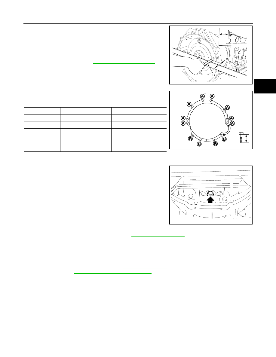
• When installing A/T assembly to the engine assembly, be sure to

check distance (A) to ensure it is within the reference value limit.

• When installing A/T assembly to the engine assembly, attach the

fixing bolts in accordance with the following standard.

*: Tightening the bolt with air breather vent.

• Align the positions of tightening bolts for drive plate with those of

the torque converter, and temporarily tighten the bolts. Then,
tighten the bolts with the specified torque.

CAUTION:

• When turning crankshaft, turn it clockwise as viewed from the

front of the engine.

• When tightening the tightening bolts for the torque converter

after fixing the crankshaft pulley bolts, be sure to confirm the
tightening torque of the crankshaft pulley mounting bolts.
Refer to 

EM-48, "Exploded View"

.

• Rotate crankshaft several turns and check to be sure that A/T

rotates freely without binding after converter is installed to
drive plate.

• Install crankshaft position sensor (POS). Refer to 

EM-110, "Exploded View"

.

Inspection

INFOID:0000000001672290

INSPECTION AFTER INSTALLATION

Check the following item after completing installation.
• A/T fluid leakage and A/T fluid level. Refer to 

TM-214, "Inspection"

.

• A/T position. Refer to 

TM-226, "Inspection and Adjustment"

.

B

:  Scale

C

: Straightedge

Distance (A)

: Refer to 

TM-330, "Torque Converter"

JPDIA0042ZZ

Transmission to engine

Engine to transmission

Bolt No.

A

B

Number of bolts

8

4

Bolt length
mm (in)

65 (2.56)

35 (1.38)

Tightening torque
N·m (kg-m, ft-lb)

75 (7.7, 55)

46.6 (4.8, 34)

JSDIA0506ZZ

JPDIA0044ZZ

TM-266

< DISASSEMBLY AND ASSEMBLY >

[5AT: RE5R05A]

TRANSMISSION ASSEMBLY

DISASSEMBLY AND ASSEMBLY

TRANSMISSION ASSEMBLY

Exploded View

INFOID:0000000001672294

SCIA7983E

TRANSMISSION ASSEMBLY

TM-267

< DISASSEMBLY AND ASSEMBLY >

[5AT: RE5R05A]

C

E

F

G

H

I

J

K

L

M

A

B

TM

N

O

P

1.

O-ring

2.

Oil pump cover

3.

O-ring

4.

Oil pump housing

5.

Self-sealing bolt

6.

Torque converter

7.

Converter housing

8.

Oil pump housing oil seal

9.

Bearing race

10.

Needle bearing

11.

O-ring

12.

Front carrier assembly

13.

Needle bearing

14.

Snap ring

15.

Front sun gear

16.

3rd one-way clutch

17.

Snap ring

18.

Bearing race

19.

Needle bearing

20.

Seal ring

21.

Input clutch assembly

22.

Needle bearing

23.

Rear internal gear

24.

Brake band

25.

Mid carrier assembly

26.

Needle bearing 

27.

Bearing race

28.

Rear carrier assembly

29.

Needle bearing 

30.

Mid sun gear

31.

Seal ring

32.

Rear sun gear

33.

1st one-way clutch

34.

Snap ring

35.

Needle bearing

36.

High and low reverse clutch hub

37.

Snap ring

38.

Bearing race

39.

Needle bearing

: Apply Genuine RTV silicone sealant or equivalent. Refer to 

GI-15, "Recommended Chemical Products and Sealants"

.

Refer to 

GI-4, "Components"

 for symbols not described on the above.

TM-268

< DISASSEMBLY AND ASSEMBLY >

[5AT: RE5R05A]

TRANSMISSION ASSEMBLY

1.

Needle bearing

2.

Bearing race

3.

High and low reverse clutch assembly

4.

Needle bearing

5.

Direct clutch assembly

6.

Reverse brake dish plate

7.

Reverse brake dish plate

8.

Reverse brake driven plate

9.

N-spring

10. Reverse brake drive plate

11.

Reverse brake retaining plate

12. Snap ring

13. D-ring

14. D-ring

15. Reverse brake piston

SCIA8365E


Content   ..  1351  1352  1353  1354   ..