Content .. 1350 1351 1352 1353 ..
Infiniti G37 Coupe. Manual - part 1352
A/T FLUID COOLER TUBE
TM-261
< ON-VEHICLE REPAIR >
[5AT: RE5R05A]
C
E
F
G
H
I
J
K
L
M
A
B
TM
N
O
P
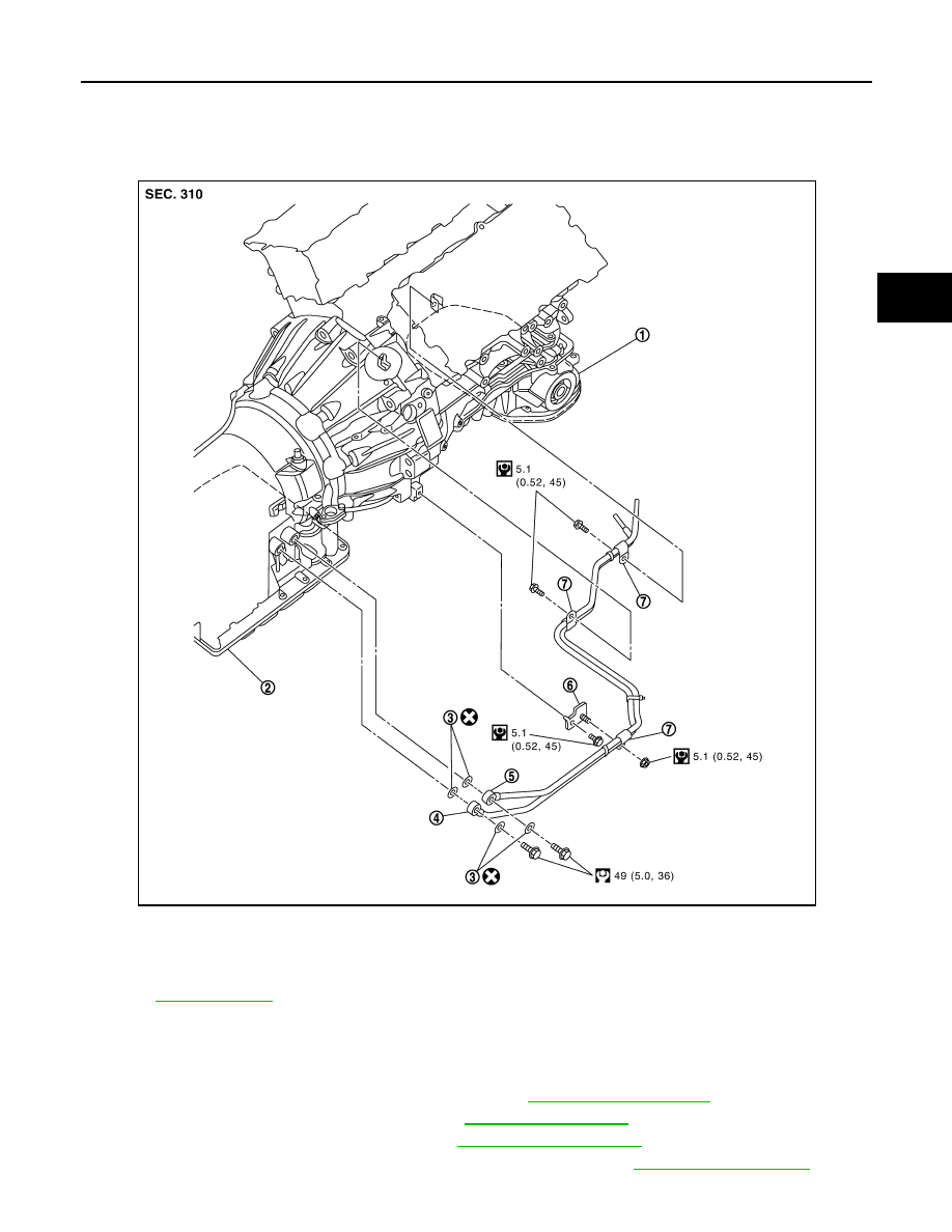
A/T FLUID COOLER TUBE
Exploded View
INFOID:0000000001672282
Removal and Installation
INFOID:0000000001672283
REMOVAL
1.
Remove the engine lower cover with power tool. Refer to
2.
Remove the exhaust mounting bracket. Refer to
3.
Remove the suspension member stay. Refer to
4.
Pull out the A/T fluid cooler hose from the A/T fluid cooler tube. Refer to
1.
Engine assembly
2.
A/T assembly
3.
Copper washer
4.
A/T fluid cooler tube
5.
A/T fluid cooler tube
6.
Bracket
7.
Clip
Refer to
JPDIA0554GB