Content .. 1345 1346 1347 1348 ..
Infiniti G37 Coupe. Manual - part 1347
A/T FLUID TEMPERATURE SENSOR 2
TM-241
< ON-VEHICLE REPAIR >
[5AT: RE5R05A]
C
E
F
G
H
I
J
K
L
M
A
B
TM
N
O
P
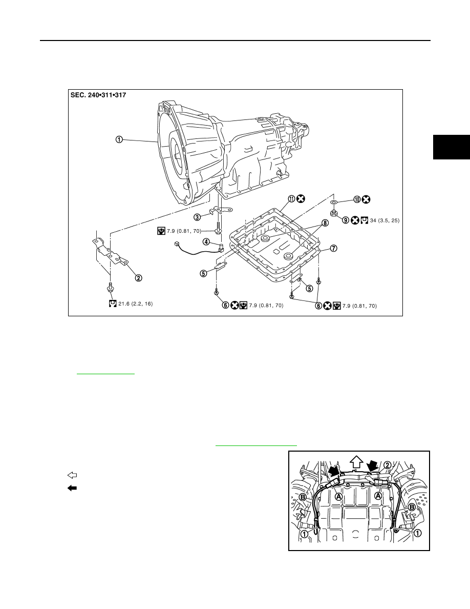
A/T FLUID TEMPERATURE SENSOR 2
Exploded View
INFOID:0000000001672263
Removal and Installation
INFOID:0000000001672264
REMOVAL
1.
Disconnect the battery cable from the negative terminal.
2.
Drain ATF through drain plug.
3.
Remove exhaust mounting bracket. Refer to
4.
Disconnect heated oxygen sensor 2 harness connectors (A).
5.
Remove heated oxygen sensor 2 harness (B) from clips (1).
6.
Remove bracket (2) from transmission assembly.
1.
A/T
2.
Bracket
3.
Bracket
4.
A/T fluid temperature sensor 2
5.
Clip
6.
Oil pan mounting bolt
7.
Oil pan
8.
Magnet
9.
Drain plug
10. Drain plug gasket
11.
Oil pan gasket
Refer to
JSDIA0123GB
: Vehicle front
: Bolt
SCIA8269E