Content .. 1342 1343 1344 1345 ..
Infiniti G37 Coupe. Manual - part 1344
CONTROL ROD
TM-229
< ON-VEHICLE REPAIR >
[5AT: RE5R05A]
C
E
F
G
H
I
J
K
L
M
A
B
TM
N
O
P
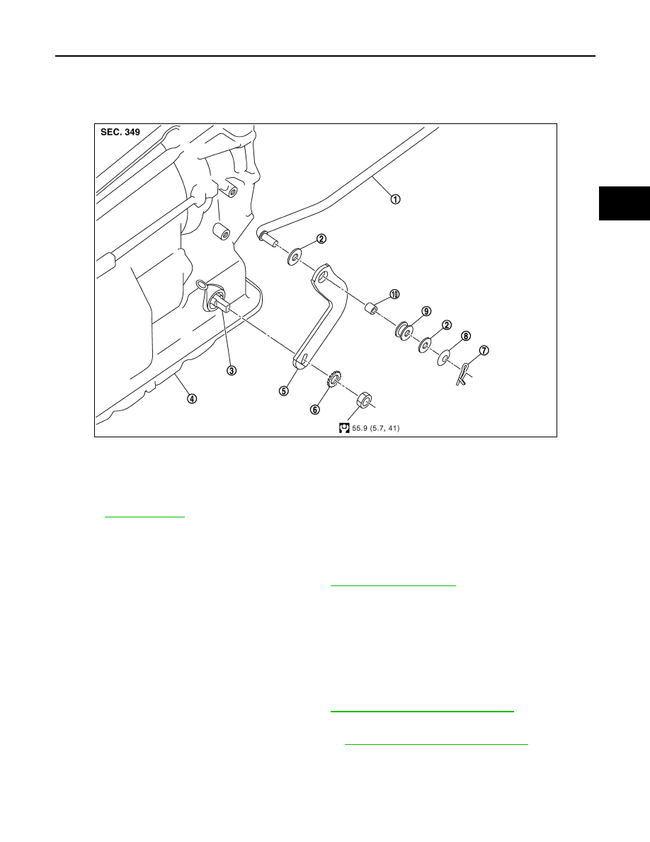
CONTROL ROD
Exploded View
INFOID:0000000001672252
Removal and Installation
INFOID:0000000001672253
REMOVAL
1.
Disconnect control device and control rod. Refer to
.
2.
Remove manual lever from A/T assembly.
3.
Remove control rod from manual lever.
INSTALLATION
Install in the reverse order of removal.
Inspection and Adjustment
INFOID:0000000001672254
ADJUSTMENT AFTER INSTALLATION
Adjust A/T positions after installing control rod. Refer to
TM-226, "Inspection and Adjustment"
.
INSPECTION AFTER INSTALLATION
Check A/T positions after adjusting A/T positions. Refer to
TM-226, "Inspection and Adjustment"
1.
Control rod
2.
Plain washer
3.
Manual shaft
4.
A/T assembly
5.
Manual lever
6.
Washer
7.
Snap pin
8.
Conical washer
9.
Insulator
10.
Collar
for symbols in the figure.
JPDIA0004GB