Infiniti G37 Coupe. Manual - part 1307


  Index      Infiniti     Infiniti G37 Coupe - service repair manual 2008 year


Search            


Content   ..  1305  1306  1307  1308   ..


Infiniti G37 Coupe. Manual - part 1307


A/T CONTROL SYSTEM

TM-81

< FUNCTION DIAGNOSIS >

[5AT: RE5R05A]

C

E

F

G

H

I

J

K

L

M

A

B

TM

N

O

P

• *1: Spare for vehicle speed sensor·A/T (revolution sensor)

• *2: Spare for accelerator pedal position signal

• *3: If these input and output signals are different, the TCM triggers the fail-safe function.

• *4: Used as a condition for starting self-diagnostics; if self-diagnostics are not started, it is judged that there is some kind of error.

• *5: Input by CAN communications.

• *6: Output by CAN communications.

CAN COMMUNICATION

CAN (Controller Area Network) is a serial communication line for real-time application. It is an on-vehicle mul-
tiplex communication line with high data communication speed and excellent error detection ability. Many elec-
tronic control units are equipped onto a vehicle, and each control unit shares information and links with other
control units during operation (not independently). In CAN communication, control units are connected with 2
communication lines (CAN-H line, CAN-L line) allowing a high rate of information transmission with less wiring.
Each control unit transmits/receives data but selectively reads required data only. Refer to 

LAN-25, "CAN

Communication Signal Chart"

.

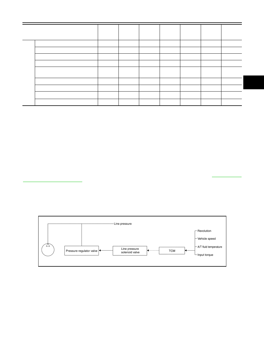
LINE PRESSURE CONTROL

• When an input torque signal equivalent to the engine drive force is transmitted from the ECM to the TCM,

the TCM controls the line pressure solenoid valve.

• This line pressure solenoid controls the pressure regulator valve as the signal pressure and adjusts the pres-

sure of the operating oil discharged from the oil pump to the line pressure most appropriate to the driving
state.

Line Pressure Control is Based On The TCM Line Pressure Characteristic Pattern

• The TCM has stored in memory a number of patterns for the optimum line pressure characteristic for the

driving state.

• In order to obtain the most appropriate line pressure characteristic to meet the current driving state, the TCM

controls the line pressure solenoid current value and thus controls the line pressure.

Normal Control

Out-
put

Direct clutch solenoid

X

X

X

X

Input clutch solenoid

X

X

X

X

High and low reverse clutch solenoid

X

X

X

X

Front brake solenoid

X

X

X

X

Low coast brake solenoid
(ATF pressure switch 2)

X

X

X

X

X

Line pressure solenoid

X

X

X

X

X

X

X

TCC solenoid

X

X

X

Self-diagnostics table

*6

X

Starter relay

X

X

Control item

Line

pressure

control

Vehicle 

speed 

control

Shift     

control

Lock-up 

control

Engine 

brake 

control

Fail-safe 

function 

*3

Self-diag-

nostics 

function

PCIA0007E

TM-82

< FUNCTION DIAGNOSIS >

[5AT: RE5R05A]

A/T CONTROL SYSTEM

• Each clutch is adjusted to the necessary pressure to match the

engine drive force.

Back-up Control (Engine Brake)

• When the select operation is performed during driving and the A/T

is shifted down, the line pressure is set according to the vehicle
speed.

During Shift Change

• The necessary and adequate line pressure for shift change is set.

For this reason, line pressure pattern setting corresponds to input
torque and gearshift selection. Also, line pressure characteristic
corresponds to engine speed, during engine brake operation.

At Low Fluid Temperature

PCIA0008E

PCIA0009E

PCIA0010E

A/T CONTROL SYSTEM

TM-83

< FUNCTION DIAGNOSIS >

[5AT: RE5R05A]

C

E

F

G

H

I

J

K

L

M

A

B

TM

N

O

P

• When the A/T fluid temperature drops below the prescribed tem-

perature, in order to speed up the action of each friction element,
the line pressure is set higher than the normal line pressure char-
acteristic.

SHIFT CONTROL

The clutch pressure control solenoid is controlled by the signals from the switches and sensors. Thus, the
clutch pressure is adjusted to be appropriate to the engine load state and vehicle driving state. It becomes
possible to finely control the clutch hydraulic pressure with high precision and a smoother shift change charac-
teristic is attained.

Shift Change

The clutch is controlled with the optimum timing and oil pressure by the engine speed, engine torque informa-
tion, etc.

Shift Change System Diagram

*1: Full phase real-time feedback control monitors movement of gear ratio at gear change, and controls oil
pressure in real-time to achieve the best gear ratio.

Blipping Control

This system makes transmission clutch engage readily by controlling (synchronizing) engine revolution
according to the (calculation of) engine revolution after shifting down.
• “BLIPPING CONTROL” functions.
- When downshifting by accelerator pedal depression at “D” position.
- When downshifting under the manual mode.
• TCM selects “BLIPPING CONTROL” or “NORMAL SHIFT CONTROL” according to the gear position, the

selector lever position, the engine torque and the speed when accelerating by pedal depression.

PCIA0011E

PCIA0012E

PCIA0013E

TM-84

< FUNCTION DIAGNOSIS >

[5AT: RE5R05A]

A/T CONTROL SYSTEM

• Revolution control demand signal is transmitted from TCM to ECM under “BLIPPING CONTROL”.
• TCM synchronizes engine revolution according to the revolution control demand signal.

Shift Change System Diagram

ASC (Adoptive Shift Control)

ASC automatically shifts or hold at the 2nd, 3rd or 4th gear on certain roads (up/down slope and curve) and
driving condition.

When Driving On an Up/Down Slope

• ASC judges up/down slope according to engine torque data transmitted from the ECM and vehicle speed.

Holding gear at the 3rd or 4th on an up-slope prevents shift hunting and controls the vehicle to gain optimum
driving force. On a down-slope, automatic shift-down to the 3rd or 4th gear controls to gain optimum engine
brake.

When Driving On a Curve

• TCM receives the lateral G sensor signal from the ABS actuator control unit. It locks the gear to the 3rd or

4th position in moderate cornering or to the 2nd position in sharp cornering based on this signal. This pre-
vents any upshift and kickdown during cornering, maintaining smooth vehicle travel.

DS Mode

• Changes to the shift schedule that mainly utilizes the high engine speed zone when ASC is active.
• DS mode can be switched according to the following method.
- When the selector lever is in the “D” position, shifting the selector lever to manual shift gate enables switch-

ing to DS mode.

- When in DS mode, shifting the selector lever to the main gate enables to cancel DS mode.

SCIA6483E

SCIA6469E


Content   ..  1305  1306  1307  1308   ..