Infiniti G37 Coupe. Manual - part 1297


  Index      Infiniti     Infiniti G37 Coupe - service repair manual 2008 year


Search            


Content   ..  1295  1296  1297  1298   ..


Infiniti G37 Coupe. Manual - part 1297


TRANSMISSION ASSEMBLY

TM-41

< DISASSEMBLY AND ASSEMBLY >

[6MT: FS6R31A]

C

E

F

G

H

I

J

K

L

M

A

B

TM

N

O

P

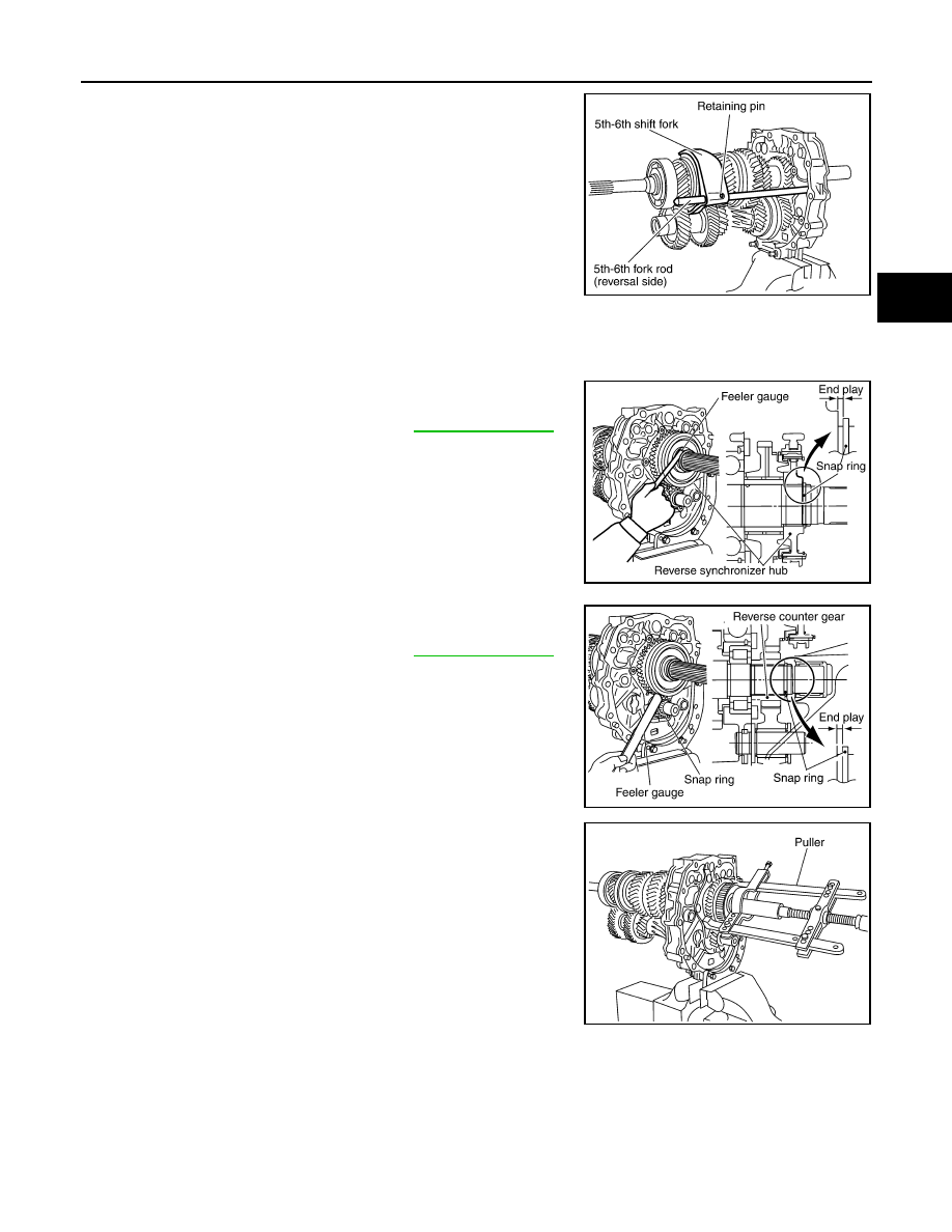
16. Remove retaining pin using a pin punch and then remove 5th-

6th fork rod (reversal side) and 5th-6th shift fork.

SHAFT AND GEAR

1.

Before disassembly, measure end play for each position. If the end play is outside the specifications, dis-
assemble and inspect.
• Mainshaft

• Counter shaft

2.

After removing snap ring and reverse coupling snap ring, using
a puller to remove reverse main gear and reverse synchronizer
assembly.

3.

Remove reverse main needle bearing.

PCIB0412E

End play standard value

: Refer to 

TM-75, "End Play"

.

PCIB0722E

End play standard value

: Refer to 

TM-75, "End Play"

.

PCIB0723E

SCIA1683E

TM-42

< DISASSEMBLY AND ASSEMBLY >

[6MT: FS6R31A]

TRANSMISSION ASSEMBLY

4.

After removing snap ring, using the puller to remove reverse
counter gear and counter rear bearing spacer.

5.

Remove mainshaft bearing retainer mounting bolts and then
remove mainshaft bearing retainer.

6.

Remove snap ring from mainshaft bearing.

7.

Carefully tap mainshaft with a plastic hammer and then remove
mainshaft assembly, main drive gear assembly and counter
shaft assembly from adapter plate.

8.

Remove main pilot bearing, pilot bearing spacer and 5th baulk
ring.

9.

Remove counter rear bearing from adapter plate.

10. Remove magnet from adapter plate.

SCIA1682E

PCIB1238E

SCIA1691E

SCIA1456E

PCIB0244E

TRANSMISSION ASSEMBLY

TM-43

< DISASSEMBLY AND ASSEMBLY >

[6MT: FS6R31A]

C

E

F

G

H

I

J

K

L

M

A

B

TM

N

O

P

Assembly

INFOID:0000000001732881

SHAFT AND GEAR

1.

Install main drive gear assembly, mainshaft assembly and counter gear assembly according to the follow-
ing.

a.

Install main pilot bearing, pilot bearing spacer and 5th baulk ring to main drive gear.

b.

Install main drive gear assembly, mainshaft assembly, and
counter shaft assembly combined in one unit to adapter plate
using brass bar.

2.

Install the adapter setting plate to adapter plate and then fixing
in adapter setting plate using a vise.

CAUTION:

Never directly secure the surface in a vise. 

3.

Install magnet to adapter plate.

4.

Install snap ring to mainshaft bearing.

CAUTION:

Never reuse snap ring.

5.

Install counter rear bearing onto adapter plate using the drift.

CAUTION:

Replace counter rear bearing inner race, counter rear bear-
ing and counter rear bearing spacer as a set.

PCIB0151E

PCIB1266E

SCIA1691E

PCIB1375E

TM-44

< DISASSEMBLY AND ASSEMBLY >

[6MT: FS6R31A]

TRANSMISSION ASSEMBLY

6.

Apply thread locking sealant to the end of bolts (first 3 to 4
threads).
• Use Genuine Medium Strength Thread Locking Sealant or

an equivalent. Refer to 

GI-15, "Recommended Chemical

Products and Sealants"

.

CAUTION:

Remove old sealant and oil adhering to threads.

7.

Install bolts into mainshaft bearing retainer and tighten bolts to
the specified torque.

8.

Install reverse coupling sleeve and reverse shifting inserts into reverse synchronizer hub.

CAUTION:

• Install reverse coupling sleeve with the flat flange on the

rear side.

• Never reuse reverse coupling sleeve and reverse syn-

chronizer hub.

• Replace reverse coupling sleeve and reverse synchro-

nizer hub as a set.

9.

Install reverse spread springs in reverse shifting inserts.

CAUTION:

• Never install reverse spread spring hook onto the same

reverse shifting insert.

• Be careful with the shape of 1st-2nd, 3rd-4th and 5th-6th

shifting insert to avoid misassembly.

10. Install snap ring to reverse synchronizer hub.

CAUTION:

PCIB1238E

PCIB0617E

SCIA1600E

PCIB0608E


Content   ..  1295  1296  1297  1298   ..