Infiniti G37 Coupe. Manual - part 1296


  Index      Infiniti     Infiniti G37 Coupe - service repair manual 2008 year


Search            


Content   ..  1294  1295  1296  1297   ..


Infiniti G37 Coupe. Manual - part 1296


TRANSMISSION ASSEMBLY

TM-37

< DISASSEMBLY AND ASSEMBLY >

[6MT: FS6R31A]

C

E

F

G

H

I

J

K

L

M

A

B

TM

N

O

P

19. Remove baffle plate mounting nut from transmission case.

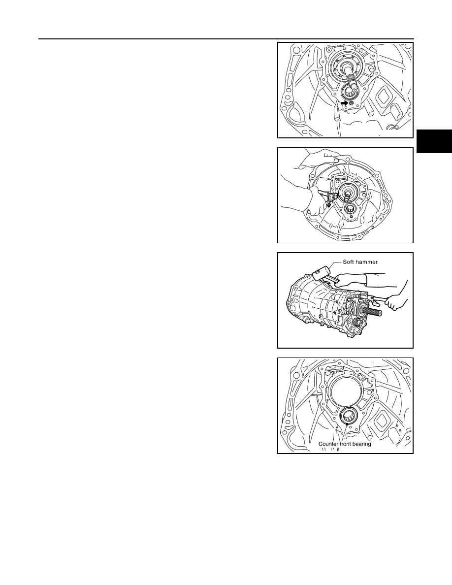
20. Remove snap ring from main drive gear bearing using snap ring

pliers.

21. Using a soft hammer to carefully tap mainshaft and counter shaft

from transmission case side and then separate adapter plate
and transmission case.

22. Remove counter front bearing from transmission case.

23. Remove oil gutter and breather tube from transmission case.
24. Remove filler plug, drain plug, and gaskets from transmission

case.

25. Remove bracket mounting bolt and then remove bracket from

transmission case.

SHIFT FORK AND FORK ROD

SCIA1443E

SCIA1532E

SCIA1687E

PCIB0436E

TM-38

< DISASSEMBLY AND ASSEMBLY >

[6MT: FS6R31A]

TRANSMISSION ASSEMBLY

1.

Install adapter setting plate [SST: ST22490000 (

)] to

adapter plate and then fixing in adapter setting plate using a
vise.

CAUTION:

Never directly secure the surface in a vise. 

2.

Remove baffle plate mounting bolts and then remove baffle
plate from adapter plate.

3.

Remove retaining pin using a pin punch and then remove strik-
ing lever and striking rod. 

4.

Remove check ball plugs and then remove check ball springs
and check balls from adapter plate.

5.

Remove 3rd-4th control lever mounting bolts and then remove
3rd-4th control lever and shifter cap.

CAUTION:

Never lose shifter cap.

PCIB0254E

PCIB0154E

PCIB0414E

PCIB0143E

PCIB0235E

TRANSMISSION ASSEMBLY

TM-39

< DISASSEMBLY AND ASSEMBLY >

[6MT: FS6R31A]

C

E

F

G

H

I

J

K

L

M

A

B

TM

N

O

P

6.

Remove check ball plug and then remove check ball spring and
check ball from adapter plate.

7.

Remove retaining pin using a pin punch and then remove 3rd-
4th fork rod bracket and 3rd-4th fork rod.

8.

Remove retaining pin using a pin punch and then remove 3rd-
4th shift fork and 3rd-4th fork rod (reversal side).

9.

Remove check balls and interlock pin from adapter plate.

10. Remove retaining pin using a pin punch and then remove 1st-

2nd shift fork and 1st-2nd fork rod.

PCIB0144E

PCIB0145E

PCIB0601E

PCIB0146E

PCIB0602E

TM-40

< DISASSEMBLY AND ASSEMBLY >

[6MT: FS6R31A]

TRANSMISSION ASSEMBLY

11. Remove interlock plunger and interlock pin from adapter plate.

12. Remove retaining pin using a pin punch and then remove

reverse shift fork and reverse fork rod.

13. Remove check balls from adapter plate.

14. Remove 5th-6th control lever mounting bolts and then remove

5th-6th control lever from adapter plate.

15. Remove retaining pin using a pin punch and then remove 5th-

6th fork rod bracket and 5th-6th fork rod.

PCIB0147E

SCIA1447E

PCIB0148E

PCIB0238E

PCIB0239E


Content   ..  1294  1295  1296  1297   ..