Content .. 1284 1285 1286 1287 ..
Infiniti G37 Coupe. Manual - part 1286
STARTER MOTOR
STR-15
< ON-VEHICLE REPAIR >
C
D
E
F
G
H
I
J
K
L
M
A
STR
N
P
O
ON-VEHICLE REPAIR
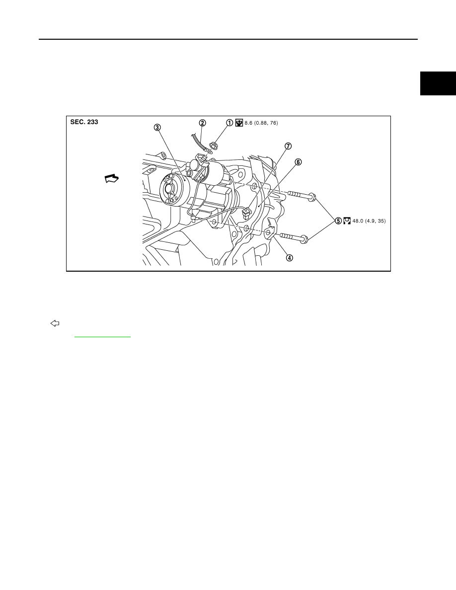
STARTER MOTOR
Exploded View
INFOID:0000000001665990
REMOVAL
DISASSEMBLY
Type: S114-932
1.
“B” terminal nut
2.
“B” terminal harness
3.
Starter motor
4.
Harness clip bracket
5.
Starter motor mounting bolt
6.
Converter housing (A/T models)
Transmission case (M/T models)
7.
“S” connector
: Vehicle front
Refer to
JPBIA0147GB