Infiniti G37 Coupe. Manual - part 1264


  Index      Infiniti     Infiniti G37 Coupe - service repair manual 2008 year


Search            


Content   ..  1262  1263  1264  1265   ..


Infiniti G37 Coupe. Manual - part 1264


C1917, C1918 REAR WHEEL STEERING ANGLE SENSOR

STC-107

< COMPONENT DIAGNOSIS >

[WITH 4WAS]

C

D

E

F

H

I

J

K

L

M

A

B

STC

N

O

P

C1917, C1918 REAR WHEEL STEERING ANGLE SENSOR

Description

INFOID:0000000001666421

• It detects the steering angle condition of rear wheel.
• 2 systems (main and sub sensor) are equipped.

DTC Logic

INFOID:0000000001666422

DTC DETECTION LOGIC

DTC CONFIRMATION PROCEDURE

1.

RECHECK DTC

With CONSULT-III

1.

 Start the engine.

CAUTION:

Stop the vehicle.

2.

Perform the active test.

3.

Perform 4WAS main control unit self-diagnosis.

Is DTC “C1917” or “C1918” detected?

YES

>> Proceed to diagnosis procedure. Refer to 

STC-107, "Diagnosis Procedure"

.

NO

>> INSPECTION END

Diagnosis Procedure

INFOID:0000000001666423

1.

CHECK REAR WHEEL STEERING ANGLE SENSOR (1)

With CONSULT-III

1.

 Start engine.

CAUTION:

Check condition with the vehicle stopped.

2.

Check “RR ST ANG-MAI” and “RR ST ANG-SUB” item on “DATA MONITOR” of 4WAS main control unit.

Is the inspection result normal?

YES

>> GO TO 2.

NO

>> Replace 4WAS rear actuator. Refer to 

STC-180, "Exploded View"

.

2.

CHECK REAR WHEEL STEERING ANGLE SENSOR (2)

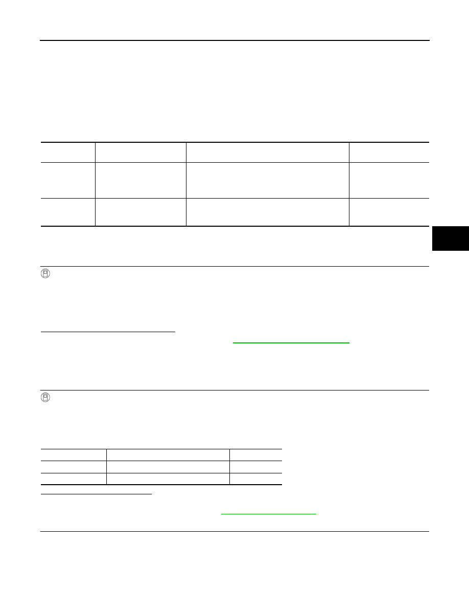
Check the voltage between 4WAS main control unit harness connector terminal and ground.

DTC

Items

(CONSULT-III screen terms)

Diagnostic item is detected when...

Possible cause

C1917

RR ST ANGLE SENSOR
[OFFSET SIG1]

The rear wheel angle sensor signal (main and sub) er-
ror is detected.
(The output signal value differs temporarily between 
main and sub.)

Rear wheel steering sen-
sor (main and sub) output 
signal value error signal

C1918

RR ST ANGLE SENSOR
[OFFSET SIG2]

The rear wheel angle sensor signal (main and sub) er-
ror is detected.
(The output signal value differs between main and sub.)

Rear wheel steering sen-
sor (main and sub) output 
signal error

Monitored item

Condition

Display value

RR ST ANG-MAI

Straight-ahead

Approx. 2.4 V

RR ST ANG-SUB

Straight-ahead

Approx. 2.6 V

STC-108

< COMPONENT DIAGNOSIS >

[WITH 4WAS]

C1917, C1918 REAR WHEEL STEERING ANGLE SENSOR

Is the differential between terminal voltage No. 4 and No.7 approximately 1 V or more?

YES 

>> Replace 4WAS main control unit. Refer to 

STC-178, "Exploded View"

.

NO

>> GO TO 3.

3.

CHECK REAR WHEEL STEERING ANGLE SENSOR (3)

1.

Turn the ignition switch OFF.

2.

Disconnect rear wheel steering angle sensor harness connector.

3.

Check resistance between rear wheel steering angle sensor connector terminals.

Is the inspection result normal?

YES

>> GO TO 4.

NO

>> Replace 4WAS rear actuator. Refer to 

STC-180, "Exploded View"

.

4.

CHECK REAR WHEEL STEERING ANGLE SENSOR GROUND CIRCUIT

1.

Disconnect 4WAS main control unit harness connector.

2.

Check for continuity between 4WAS main control unit harness connector terminal and rear wheel steering
angle sensor harness connector terminal.

Is the inspection result normal?

YES

>> GO TO 5.

NO

>> Repair or replace each harness and connector.

5.

RERFORM SELF-DIAGNOSIS (4WAS MAIN CONTROL UNIT)

With CONSULT-III

1.

Connect 4WAS main control unit harness connector.

2.

Connect rear wheel steering angle sensor harness connector.

3.

Perform 4WAS main control unit self-diagnosis.

Is DTC “C1917” or “C1918” detected?

YES

>> Replace 4WAS main control unit. Refer to 

STC-178, "Exploded View"

.

NO

>> GO TO 6.

4WAS main control unit

Voltage (Approx.)

Connector

Terminal

B54

4 – Ground

2.4 V

7 – Ground

2.6 V

Rear wheel steering angle sensor

Resistance (Approx.)

Connector

Terminal

B35

1 – 3

1 k

1 – 2

1.2 – 1.5 k

1 – 4

1.2 – 1.5 k

4WAS main control unit

Rear wheel steering angle 

sensor

Continuity

Connector

Terminal

Connector

Terminal

B54

4

B35

1, 2, 3

Not existed

B54

4

B35

4

Existed

B54

7

B35

1, 3, 4

Not existed

B54

7

B35

2

Existed

B54

5

B35

1

Existed

B54

5

B35

2, 3, 4

Not existed

B54

15

B35

1, 2, 4

Not existed

B54

15

B35

3

Existed

C1917, C1918 REAR WHEEL STEERING ANGLE SENSOR

STC-109

< COMPONENT DIAGNOSIS >

[WITH 4WAS]

C

D

E

F

H

I

J

K

L

M

A

B

STC

N

O

P

6.

CHECK INFORMATION

With CONSULT-III

Check the “DATA MONITOR” value of each DTC detected with the self-diagnosis function. Refer to 

STC-155,

"Reference Value"

.

Is each data standard?

YES

>> Check pin terminal and connection of each harness connector for non-standard conditions.

NO

>> Replace 4WAS main control unit. Refer to 

STC-178, "Exploded View"

.

Component Inspection

INFOID:0000000001666424

1.

CHECK REAR WHEEL STEERING ANGLE SENSOR

1.

Turn the ignition switch OFF.

2.

Disconnect rear wheel steering angle sensor harness connector.

3.

Check the resistance between rear wheel steering angle sensor connector terminals.

Is the inspection result normal?

YES

>> INSPECTION END

NO

>> Replace 4WAS rear actuator. Refer to 

STC-180, "Exploded View"

.

Special Repair Requirement

INFOID:0000000001666425

BEFORE REPLACING 4WAS MAIN CONTROL UNIT

• Record the self-diagnosis results (history).

CAUTION:

• Never erase the memory (history) of self-diagnosis results when replacing 4WAS main control unit

after diagnosis.

• Erase the memory of the self-diagnosis results (record) after printing out or recording all the val-

ues of “DATA MONITOR”.

Rear wheel steering angle sensor

Resistance (Approx.)

Connector

Terminal

B35

1 – 3

1 k

1 – 2

1.2 – 1.5 k

1 – 4

1.2 – 1.5 k

STC-110

< COMPONENT DIAGNOSIS >

[WITH 4WAS]

C1919 VEHICLE SPEED SIGNAL

C1919 VEHICLE SPEED SIGNAL

Description

INFOID:0000000001666426

• The vehicle speed signal is transmitted from ABS actuator and electric unit (control unit) to 4WAS main con-

trol unit via CAN communication.

DTC Logic

INFOID:0000000001666427

DTC DETECTION LOGIC

DTC CONFIRMATION PROCEDURE

1.

RECHECK DTC

With CONSULT-III

1.

Turn the ignition switch from OFF to ON.

2.

Perform 4WAS main control unit self-diagnosis.

Is DTC “C1919” detected?

YES

>> Proceed to diagnosis procedure. Refer to 

STC-110, "Diagnosis Procedure"

.

NO

>> INSPECTION END

Diagnosis Procedure

INFOID:0000000001666428

1.

PERFORM ABS ACTUATOR AND ELECTRIC UNIT (CONTROL UNIT) SELF-DIAGNOSIS

With CONSULT-III

 Perform ABS actuator and electrical unit (control unit) self-diagnosis. 

Is any error system detected?

YES

>> Check the error system.

NO

>> GO TO 2.

2.

PERFORM SELF-DIAGNOSIS (4WAS MAIN CONTROL UNIT)

With CONSULT-III

Perform 4WAS main control unit self-diagnosis.
Is DTC “U1000” or “U1010” detected?

YES

>> Check the error system.

NO

>> GO TO 3.

3.

PERFORM SELF-DIAGNOSIS (4WAS MAIN CONTROL UNIT)

With CONSULT-III

Perform 4WAS main control unit self-diagnosis.

Is DTC “C1919” detected?

YES

>> Replace 4WAS main control unit. Refer to 

STC-178, "Exploded View"

.

NO

>> GO TO 4.

4.

INFORMATION CHECK

With CONSULT-III

Check the “DATA MONITOR” value of each DTC detected with the self-diagnosis function. Refer to 

STC-155,

"Reference Value"

.

Is each data the standard value?

DTC

Items

(CONSULT-III screen terms)

Diagnostic item is detected when...

Possible cause

C1919

VEHICLE SPEED SEN
[NO SIGNAL]

Malfunction is detected in vehicle speed signal that is 
output from ABS actuator and electric unit (control unit) 
via CAN communication.
(Improper signal inputs while driving.)

Vehicle speed signal error


Content   ..  1262  1263  1264  1265   ..