Infiniti G37 Coupe. Manual - part 1261


  Index      Infiniti     Infiniti G37 Coupe - service repair manual 2008 year


Search            


Content   ..  1259  1260  1261  1262   ..


Infiniti G37 Coupe. Manual - part 1261


C1909 4WAS MAIN CONTROL UNIT

STC-95

< COMPONENT DIAGNOSIS >

[WITH 4WAS]

C

D

E

F

H

I

J

K

L

M

A

B

STC

N

O

P

• Open between the ignition switch and 4WAS main control unit harness connector No. 27 termi-

nal

• Ignition switch

2.

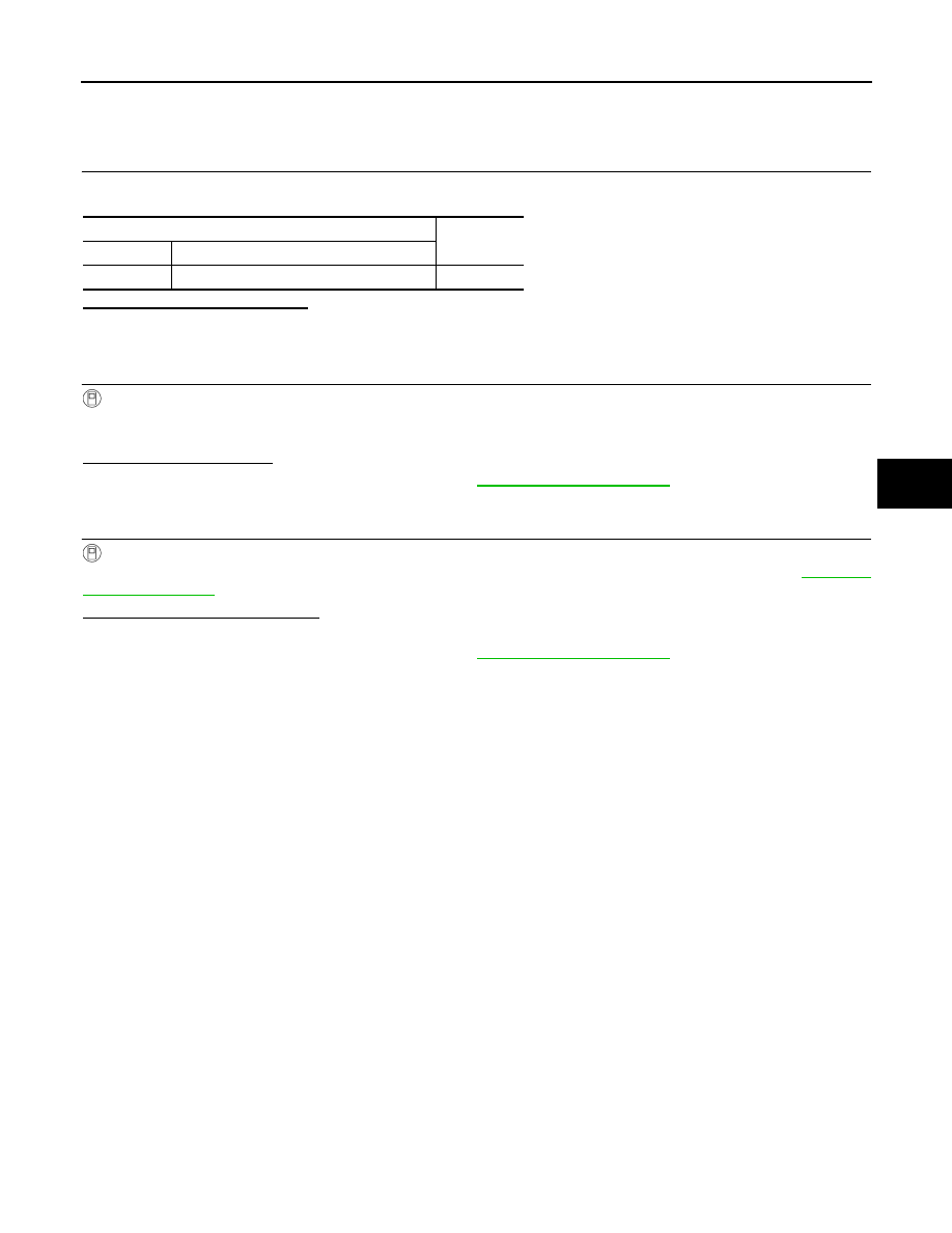
CHECK 4WAS MAIN CONTROL UNIT GROUND

Check the continuity between 4WAS main control unit harness connector and the ground.

Is the inspection result normal?

YES

>> GO TO 3.

NG

>> Repair or replace the harnesses and connectors.

3.

PERFORM SELF-DIAGNOSIS (4WAS MAIN CONTROL UNIT)

With CONSULT-III

1.

Connect 4WAS main control unit harness connector.

2.

Perform 4WAS main control unit self-diagnosis.

Is DTC “C1909” detected?

YES

>> Replace 4WAS main control unit. Refer to 

STC-178, "Exploded View"

.

NO

>> GO TO 4.

4.

CHECK INFORMATION

With CONSULT-III

Check the “DATA MONITOR” value of each DTC detected with the self-diagnosis function. Refer to 

STC-155,

"Reference Value"

.

Is each data the standard value?

YES

>> Check each harness connector pin terminal for disconnection.

NO

>> Replace 4WAS main control unit. Refer to 

STC-178, "Exploded View"

.

Special Repair Requirement

INFOID:0000000001666404

BEFORE REPLACING 4WAS MAIN CONTROL UNIT

• Record the self-diagnosis results (history).

CAUTION:

• Never erase the memory (history) of self-diagnosis results when replacing 4WAS main control unit

after diagnosis.

• Erase the memory of the self-diagnosis results (record) after printing out or recording all the val-

ues of “DATA MONITOR”.

4WAS main control unit

Continuity

Connector

Terminal

B54

34 – Ground

Existed

STC-96

< COMPONENT DIAGNOSIS >

[WITH 4WAS]

C1911, C1912 4WAS REAR MOTOR POWER SUPPLY

C1911, C1912 4WAS REAR MOTOR POWER SUPPLY

Description

INFOID:0000000001666405

• The power supply for 4WAS rear motor.

DTC Logic

INFOID:0000000001666406

DTC DETECTION LOGIC

DTC CONFIRMATION PROCEDURE

1.

RECHECK DTC

1.

Turn the ignition switch from OFF to ON.

CAUTION:

Stop the vehicle. Wait 15 minutes or more.

2.

Perform 4WAS main control unit self-diagnosis.

Is DTC “C1911” or “C1912” detected?

YES

>> Proceed to diagnosis procedure. Refer to 

STC-96, "Diagnosis Procedure"

.

NO

>> INSPECTION END

Diagnosis Procedure

INFOID:0000000001666407

1.

CHECK 4WAS MAIN CONTROL UNIT POWER SUPPLY

1.

Turn the ignition switch OFF.

2.

Disconnect 4WAS main control unit harness connector.

3.

Check the voltage between 4WAS main control unit harness connectors and the ground.

4.

Turn the ignition switch ON.

CAUTION:

Never start the engine.

5.

Check the voltage between 4WAS main control unit harness connectors and the ground.

Is the inspection result normal?

YES

>> GO TO 2.

NO

>>

Check the following items. Repair or replace the malfunctioning parts.

• 10A fuse (#45) open
- Short among 10A fuse (#45) connector, 4WAS main control unit harness connector No. 27 ter-

minal and the ground

• Open between the ignition switch and 4WAS main control unit harness connector No. 27 termi-

nal

DTC

Items

(CONSULT-III screen terms)

Diagnostic item is detected when...

Possible cause

C1911

MOTOR VOLTAGE
[LOW VOLTAGE]

4WAS rear motor voltage error is detected.
(4WAS rear motor voltage is low.)

4WAS rear motor power 
supply error

C1912

MOTOR VOLTAGE
[BAD OBSTRCT]

4WAS rear motor voltage error is detected.
(Voltage is applied to 4WAS main motor when 4WAS 
main control unit output is “OFF”.)

4WAS rear motor power 
supply error

4WAS main control unit

Voltage (Approx.)

Connector

Terminal

B54

27 – Ground

0 V

4WAS main control unit

Voltage (Approx.)

Connector

Terminal

B54

27 – Ground

Battery voltage

C1911, C1912 4WAS REAR MOTOR POWER SUPPLY

STC-97

< COMPONENT DIAGNOSIS >

[WITH 4WAS]

C

D

E

F

H

I

J

K

L

M

A

B

STC

N

O

P

• Ignition switch

2.

CHECK 4WAS REAR MOTOR POWER SUPPLY CIRCUIT (1)

1.

Turn the ignition switch OFF.

2.

Remove 4WAS rear motor relay.

3.

Check the continuity between 4WAS rear motor relay harness connector terminal and the ground.

4.

Check the continuity between 4WAS rear motor relay harness connector terminal and 4WAS main control
unit harness connector terminal.

Is the inspection result normal?

YES

>> GO TO 3.

NO

>> Repair or replace the harnesses and connectors.

3.

CHECK 4WAS REAR MOTOR POWER SUPPLY CIRCUIT (2)

Check the voltage between 4WAS rear motor relay harness connector terminal and the ground.

Is the inspection result normal?

YES

>> GO TO 4.

NO

>>

Check the following items. Repair or replace the malfunctioning parts.

• 20A fuse (#37) open
- Short among 20A fuse (#37) connector, 4WAS rear motor relay harness connector No. 3 termi-

nal and the ground

• Open between the battery and 4WAS rear motor relay harness connector No. 3 terminal

4.

CHECK 4WAS REAR MOTOR POWER SUPPLY CIRCUIT (3)

1.

Remove the noise suppressor.

2.

Check continuity between the noise suppressor harness connector terminal and the ground.

3.

Check the continuity between the noise suppressor harness connector terminal and 4WAS rear motor
relay harness connector terminal.

4WAS rear motor relay

Continuity

Connector

Terminal

B53

1 – Ground

Existed

2 – Ground

Not existed

4WAS rear motor relay

4WAS main control unit

Continuity

Connector

Terminal

Connector

Terminal

B53

2

B54

25

Existed

4WAS rear motor relay

Voltage (Approx.)

Connector

Terminal

B53

3 – Ground

Battery voltage

Noise suppressor

Continuity

Connector

Terminal

B51

3 – Ground

Not existed

5 – Ground

B52

1 – Ground

Not existed

2 – Ground

Existed

Noise suppressor

4WAS rear motor relay

Continuity

Connector

Terminal

Connector

Terminal

B52

1

B53

5

Existed

STC-98

< COMPONENT DIAGNOSIS >

[WITH 4WAS]

C1911, C1912 4WAS REAR MOTOR POWER SUPPLY

4.

Check the continuity between the noise suppressor harness connector terminal and 4WAS main control
unit harness connector terminal.

Is the inspection result normal?

YES

>> GO TO 5.

NO

>> Repair or replace the harnesses and connectors.

5.

CHECK 4WAS REAR MOTOR POWER SUPPLY CIRCUIT (4)

1.

Connect 4WAS main control unit harness connector.

2.

Turn the ignition switch ON.

CAUTION:

Never start the engine.

3.

Check the voltage between 4WAS main control unit harness connectors and the ground.

4.

Turn the ignition switch OFF.

Is the inspection result normal?

YES

>> GO TO 6.

NO

>> Replace 4WAS main control unit. Refer to 

STC-178, "Exploded View"

.

6.

CHECK 4WAS REAR MOTOR RELAY

1.

Apply 12 V to 4WAS rear motor relay connector No. 1 terminal and No. 2 terminal.

CAUTION:

• Never make the terminals short.
• Connect the fuse between the terminals when applying the voltage.

2.

Check the continuity between 4WAS rear motor relay connector terminals.

3.

Check the resistance between 4WAS rear motor relay connector terminals.

Is the inspection result normal?

YES

>> GO TO 7.

NO

>> Replace 4WAS rear motor relay.

7.

CHECK NOISE SUPPRESSOR

Check continuity between the noise suppressor connector terminals.

Noise suppressor

4WAS main control unit

Continuity

Connector

Terminal

Connector

Terminal

B51

3

B54

37

Existed

5

40

Existed

4WAS main control unit

Voltage (Approx.)

Connector

Terminal

B54

25 – Ground

Battery voltage

4WAS rear motor relay

Continuity

Connector

Terminal

Condition

B53

3 – 5

Apply the voltage between 
No. 1 terminal and No. 2 ter-
minal.

Existed

Do not apply the voltage be-
tween No. 1 terminal and 
No. 2 terminal.

Not existed

4WAS rear motor relay

Resistance (Approx.)

Connector

Terminal

B53

1 – 2

50 


Content   ..  1259  1260  1261  1262   ..