Infiniti G37 Coupe. Manual - part 1247


  Index      Infiniti     Infiniti G37 Coupe - service repair manual 2008 year


Search            


Content   ..  1245  1246  1247  1248   ..


Infiniti G37 Coupe. Manual - part 1247


DIAGNOSIS SYSTEM (4WAS FRONT CONTROL UNIT)

STC-39

< FUNCTION DIAGNOSIS >

[WITH 4WAS]

C

D

E

F

H

I

J

K

L

M

A

B

STC

N

O

P

DIAGNOSIS SYSTEM (4WAS FRONT CONTROL UNIT)

CONSULT-III Function [4WAS(FRONT)]

INFOID:0000000001666304

FUNCTION

CONSULT-III can display each diagnostic item using the diagnostic test modes shown as follows:

SELF-DIAG RESULT MODE
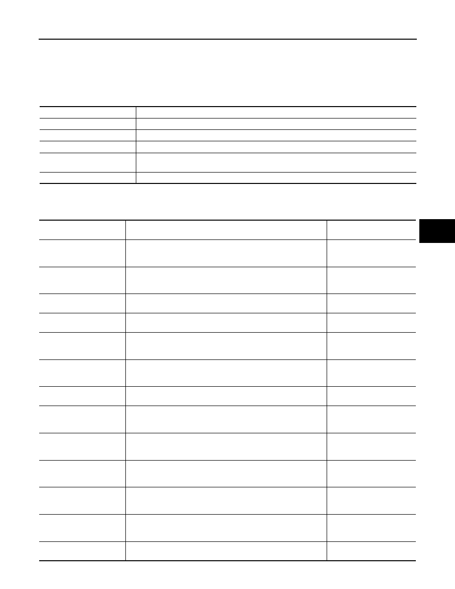
Display Item List

Diagnostic test mode

Function

Self-diagnostic results

• Self-diagnostic results can be read and erased quickly.

Data monitor

• Input/Output data in the 4WAS front control unit can be read.

CAN diagnostic support monitor

• The results of transmit/receive diagnosis of CAN communication can be read.

Active test

• Diagnostic Test Mode in which CONSULT-III drives some actuators apart from the 4WAS front 

control unit and also shifts some parameters in a specified range.

ECU part number

• 4WAS front control unit part number can be read.

Items 

(CONSULT-III screen terms)

Diagnostic item is detected when...

Possible cause

ACTUATOR
[C1621]

4WAS front motor current error is detected.
(4WAS front motor current is excessively large.)

4WAS front control unit or 
4WAS front motor error is de-
tected.

ACTUATOR
[C1622]

4WAS front motor voltage or current error is detected.
(4WAS front motor voltage error is detected.)
(Voltage or current error is detected when starting the system.)

4WAS front control unit or 
4WAS front motor error is de-
tected.

ACTUATOR
[C1627]

The indication value from 4WAS front actuator (front wheel angle) dif-
fers from the value from 4WAS front control unit.

4WAS front actuator error

ACTUATOR
[C1628]

The front wheel steering angle sensor error is detected.

Front wheel steering angle 
sensor error

CONTROL UNIT
[C1631]

An error is detected inside 4WAS front control unit.

4WAS front control unit or 
4WAS front control unit power 
supply error is detected.

CONTROL UNIT
[C1632]

An error is detected inside 4WAS front control unit.

4WAS front control unit or 
4WAS front control unit power 
supply error is detected.

CONTROL UNIT
[C1633]

An error is detected inside 4WAS front control unit.

4WAS front control unit error

IGN POWER SUPPLY
[C1651]

The ignition voltage signal error is detected.

4WAS front control unit or the 
ignition power supply error is 
detected.

MOTOR POWER SUPPLY
[C1652]

4WAS front motor main power supply error is detected.

4WAS front control unit or 
4WAS front motor power sup-
ply error is detected.

ACTUATOR RELAY
[C1654]

An error is detected on the main relay power supply inside 4WAS front 
control unit.

The main relay power supply 
inside 4WAS front control unit 
error is detected.

PRE-DRIVER
[C1655]

4WAS rear motor 3-phase current error is detected.
(Current is not applied to 4WAS front motor.)

4WAS front control unit or 
4WAS front motor power sup-
ply error is detected.

LOCK SOLENOID
[C1661]

4WAS front lock solenoid valve error is detected.
(An electric activation error is detected.)

4WAS front control unit or 
4WAS front lock solenoid 
valve error is detected.

LOCK INSERTION
[C1667]

4WAS front lock solenoid valve (lock) error is detected.
(An error is detected in lock condition.)

The inside 4WAS front actua-
tor error is detected.

STC-40

< FUNCTION DIAGNOSIS >

[WITH 4WAS]

DIAGNOSIS SYSTEM (4WAS FRONT CONTROL UNIT)

*: Communication line between 4WAS front control unit and 4WAS main control unit.

DATA MONITOR MODE

Display Item List

LOCK HLD GAP DETCT
[C1668]

4WAS front lock solenoid valve (lock) error is detected.
(Excessive force is applied to the lock.)

The inside 4WAS front actua-
tor error is detected.

INCOMP LOCK RELEAS
[C1669]

4WAS front actuator error is detected.
(An error is detected in unlock condition.)

The power steering oil pres-
sure or the inside 4WAS front 
actuator error is detected.

ACT ADJ NOT PRFRM
[C1671]

4WAS front actuator adjustment is not performed.

4WAS front actuator adjust-
ment is not performed.

INCOMP ACTUATR ADJ
[C1672]

4WAS front actuator adjustment is incomplete.

4WAS front actuator adjust-
ment is incomplete.

4WAS MAIN ECU COMM
[C1684]

4WAS communication line* data communication error is detected.
(An error signal is detected from 4WAS main control unit.)

4WAS communication line*/
4WAS main control unit/
4WAS front control unit error

4WAS MAIN ECU COMM
[C1685]

4WAS communication line* data communication error is detected.
(An error signal is detected from 4WAS main control unit.)

4WAS communication line*/
4WAS main control unit/
4WAS front control unit error

4WAS MAIN ECU
[C1686]

An error is detected on 4WAS main control unit side.
(4WAS main control unit fail-safe mode.)

4WAS main control unit fail-
safe mode

CAN COMM CIRCUIT
[U1000]

When 4WAS front control unit is not transmitting or receiving 4WAS 
communication signal for 2 seconds or more.

4WAS communication line*/
4WAS main control unit/
4WAS front control unit error

SYSTEM COMM(CAN)
[U1002]

When 4WAS front control unit is not transmitting or receiving 4WAS 
communication signal for 2 seconds or less.

4WAS communication line*/
4WAS main control unit/
4WAS front control unit error

CONTROL UNIT (CAN)
[U1010]

When detecting error during the initial diagnosis of 4WAS controller of 
4WAS front control unit.

4WAS communication line*/
4WAS main control unit/
4WAS front control unit error

Items 

(CONSULT-III screen terms)

Diagnostic item is detected when...

Possible cause

Monitor item (Unit)

Remarks

4WAS STR ANG [deg]

The steering angle sensor signal received from 4WAS main control unit via 4WAS commu-
nication line * is indicated.

VEHICLE SPEED [km/h] or [mph]

The vehicle speed signal received from 4WAS main control unit via 4WAS communication 
line * is indicated.

MOTOR CURRENT [A]

4WAS front motor power supply current is indicated.
(4WAS front control unit main power supply)

MTR CRNT ESTM [A]

The value, which 4WAS front control unit presumes 4WAS front motor power supply current, 
is indicated.
(4WAS front control unit main power supply)

ACTR ROTA ANG [deg]

4WAS front actuator increased/decreased angle is indicated.

LG VOLT [V]

4WAS front lock solenoid valve voltage is indicated.

THERM TEMP [

°

C]

4WAS front control unit internal temperature is indicated.

MOTOR VOLT [V]

4WAS front motor power supply voltage is indicated.
(4WAS front control unit main power supply)

IGN VOLT [V]

4WAS front control unit power supply voltage is indicated.
(Ignition switch power supply voltage)

ACTR ANG COMM [deg]

The command value of 4WAS front actuator increased/decreased angle received from 4WAS 
main control unit via 4WAS communication line* is indicated.

ACTR ROTA SPD [deg/s]

4WAS front actuator increased/decreased rotation speed is indicated.

DUTY COMMAND [%]

4WAS front actuator command voltage ratio is indicated.

DIAGNOSIS SYSTEM (4WAS FRONT CONTROL UNIT)

STC-41

< FUNCTION DIAGNOSIS >

[WITH 4WAS]

C

D

E

F

H

I

J

K

L

M

A

B

STC

N

O

P

LOCK DTY COMM [%]

4WAS front lock solenoid valve command voltage ratio is indicated.

MTR U VOLT [V]

4WAS front motor U terminal voltage is indicated.

MTR V VOLT [V]

4WAS front motor V terminal voltage is indicated.

MTR W VOLT [V]

4WAS front motor W terminal voltage is indicated.

ACT TEMP ESTM [

°

C]

The value, which 4WAS front control unit presumes 4WAS front actuator temperature, is in-
dicated.

MTR PHZ CRNT [A]

4WAS front motor U, V, and W terminal current is indicated.

ACTR DEVI ANG [deg]

4WAS front actuator command value and the activation angle difference are indicated.

ACTR ANGL SUB [deg]

The final command value, which 4WAS front control unit calculates 4WAS front actuator 
command value transmitted from 4WAS front control unit through 4WAS communication 
line*, is indicated.

STR ANGL SPD [deg/s]

It displays an engine speed value obtained from an angle calculated with the 4WAS front con-
trol unit, based on steering angle sensor speed signals transmitted from the 4WAS main con-
trol unit through the 4WAS communication line*.

OVRLD JDG TMG

It displays record of 4WAS system (entire 4WAS system) high load.
(It displays time of occurrence before turning ignition switch ON.)

ACT PRTCT TMG

It displays record of 4WAS system (4WAS front actuator) overheating.
(It displays time of occurrence before turning ignition switch ON.)

ECU PRTCT TMG

It displays record of 4WAS system (4WAS front control unit) overheating.
(It displays time of occurrence before turning ignition switch ON.)

DRV TMPO TMG

It displays record of 4WAS system (terminal power supply converter of 4WAS front motor) 
intermittent abnormal.
(It displays time of occurrence before turning ignition switch ON.)

MTR PW TMP TM

It displays record of 4WAS system (terminal voltage of 4WAS front motor) intermittent abnor-
mal.
(It displays time of occurrence before turning ignition switch ON.)

LOW VOLT TMG

It displays record of 4WAS system (terminal voltage of 4WAS front control unit and 4WAS 
front actuator) low voltage.
(It displays time of occurrence before turning ignition switch ON.)

HIGH VOLT TMG

It displays record of 4WAS system (terminal voltage of 4WAS front control unit and 4WAS 
front actuator) extreme voltage.
(It displays time of occurrence before turning ignition switch ON.)

OVRLD JDG FLG [On/Off]

• 4WAS system (the entire system) heavy load condition is indicated.
• 4WAS system protection function mode

ACT PRTCT FLG [On/Off]

• 4WAS system (4WAS front actuator) over-heated condition is indicated.
• 4WAS system protection function mode

ECU PRTCT FLG [On/Off]

• 4WAS system (4WAS front control unit) over-heated condition is indicated.
• 4WAS system protection function mode

DRV TMPO FLG [On/Off]

• 4WAS system (4WAS front motor terminal power supply converter) intermittent error is in-

dicated.

• 4WAS system protection function mode

MTR PW TMP FL [On/Off]

• 4WAS system (4WAS front motor terminal power supply front driver) intermittent error is 

indicated.

• 4WAS system protection function mode

LOW VOLT FLG [On/Off]

• 4WAS system (4WAS front control unit and 4WAS front actuator terminal voltage) voltage-

dropped condition

• 4WAS system protection function mode

HIGH VOLT FLG [On/Off]

• 4WAS system (4WAS front control unit and 4WAS front actuator terminal voltage) voltage-

jumped condition

• 4WAS system protection function mode

MTR SEN U OUT [Hi/Low]

4WAS front motor U terminal output voltage is indicated.

MTR SEN V OUT [Hi/Low]

4WAS front motor V terminal output voltage is indicated.

MTR SEN W OUT [Hi/Low]

4WAS front motor W terminal output voltage is indicated.

Monitor item (Unit)

Remarks

STC-42

< FUNCTION DIAGNOSIS >

[WITH 4WAS]

DIAGNOSIS SYSTEM (4WAS FRONT CONTROL UNIT)

*: Communication line between 4WAS front control unit and 4WAS main control unit

CAN DIAGNOSTIC SUPPORT MONITOR

Description

• The communication condition from 4WAS front control unit to 4WAS main control unit and malfunction

counter are displayed.

• Error counter displays OK if any malfunction is not detected in the past. If the malfunction is detected, it dis-

plays 0. The upper limit of the counters is 39.

ACTIVE TEST MODE

Description

• 4WAS front actuator assembly activation is checked according to the control signal from CONSULT-III.
• 4WAS front lock solenoid valve (lock structure) is activated forcibly (ON/OFF) using each control signal of

“LOCK OPERATION”. Perform this mode when performing 4WAS front actuator adjustment.

CAUTION:

Never steer the steering wheel during “RELEASE”.

• The steering angle sensor neutral point judgment (OK/NG) is performed using each control signal of “SLOW

MODE”.

MAIN ECU FAIL [On/Off]

4WAS main control unit fail-safe function condition transmitted from 4WAS main control unit 
through 4WAS communication line * is indicated.

M-ECU TMPO FL [On/Off]

The protection function mode status of 4WAS main control unit transmitted from 4WAS main 
control unit through 4WAS communication line* is indicated.

LOCK MODE [0/1/2/3/4/5]

4WAS front lock solenoid valve (lock structure) condition is indicated.
• 0: Lock released condition
• 1 – 5: Lock condition

NEUTRAL OUT [On/Off]

4WAS front actuator misaligned angle adjustment control condition is indicated.

EX OPERAT [On/Off]

4WAS system enters in the protection function due to the heavy load condition and tempo-
rarily abnormal voltage is indicated.

SLOW MODE [Ok/–]

ACTIVE TEST “SLOW MODE” judgment condition is indicated.

Monitor item (Unit)

Remarks

Item

PRSNT

PAST

TRANSMIT DIAG

OK / UNKWN

OK / 0 – 39

4WAS(MAIN)

OK / UNKWN

OK / 0 – 39

Select test item

Control signal

Remarks

LOCK OPERATION

RELEASE

4WAS front lock solenoid valve lock is re-
leased.

LOCK

4WAS front lock solenoid valve lock is ap-
plied.

SLOW MODE

MODE START

Steering angle sensor neutral point check 
starts.
(Turn the steering wheel rightward and left-
ward slowly. Steer until the turning stops.)

MODE END

Steering angle sensor neutral point check 
ends.


Content   ..  1245  1246  1247  1248   ..