Content .. 1233 1234 1235 1236 ..
Infiniti G37 Coupe. Manual - part 1235
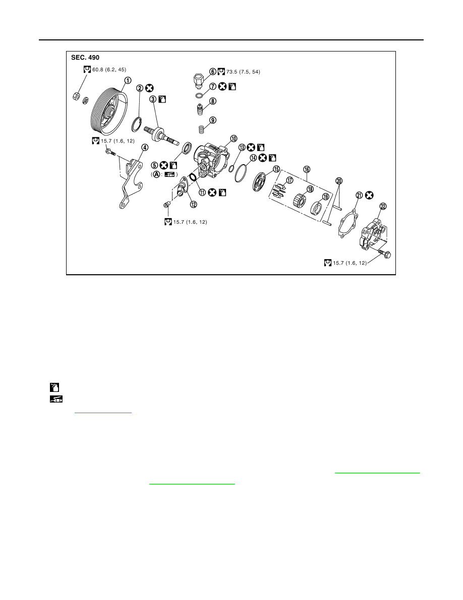
ST-40
< ON-VEHICLE REPAIR >
POWER STEERING OIL PUMP
SPORT MODELS : Removal and Installation
INFOID:0000000001666249
REMOVAL
1.
Drain power steering fluid from reservoir tank.
2.
Remove the right half of the air cleaner and the right half of the air duct. Refer to
.
3.
Loosen drive belt. Refer to
.
4.
Remove drive belt from oil pump pulley.
5.
Remove copper washers and eye bolt (drain fluid from their pipings).
6.
Remove suction hose (drain fluid from their pipings).
7.
Remove oil pump mounting bolts, and then remove oil pump.
INSTALLATION
Note the following, and install in the reverse order of removal.
1.
Pulley
2.
Snap ring
3.
Drive shaft assembly
4.
Bracket
5.
Oil seal
6.
Connector bolt
7.
O-ring
8.
Flow control valve
9.
Spring
10. Body assembly
11.
O-ring
12. Suction pipe
13. O-ring
14. O-ring
15. Side plate
16. Cartridge
17. Vane
18. Rotor
19. Cam ring
20. Dowel pin
21. Gasket
22. Rear cover
A: Oil seal lip
: Apply power steering fluid.
: Apply multi-purpose grease.
Refer to
for symbols not described on the above.
JSGIA0047GB