Infiniti G37 Coupe. Manual - part 1229


  Index      Infiniti     Infiniti G37 Coupe - service repair manual 2008 year


Search            


Content   ..  1227  1228  1229  1230   ..


Infiniti G37 Coupe. Manual - part 1229


ST-16

< ON-VEHICLE REPAIR >

STEERING COLUMN

STEERING COLUMN

WITHOUT ELECTRIC MOTOR

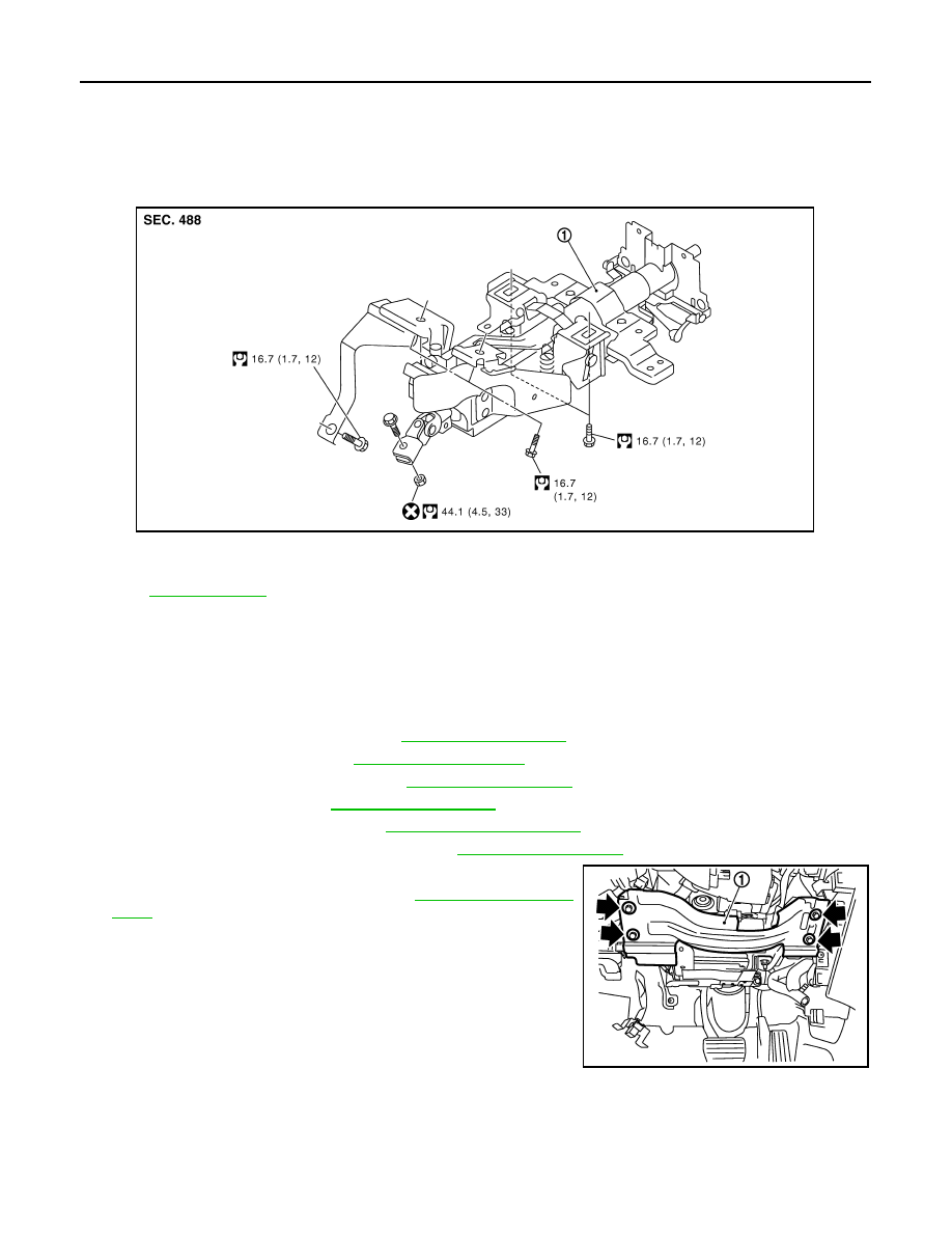
WITHOUT ELECTRIC MOTOR : Exploded View

INFOID:0000000001666223

WITHOUT ELECTRIC MOTOR : Removal and Installation

INFOID:0000000001666224

REMOVAL

1.

Set vehicle to the straight-ahead position.

2.

Place the tilt to the highest level. Place the telescopic to the longest level.

3.

Remove driver air bag module. Refer to 

SR-4, "Exploded View"

.

4.

Remove steering wheel. Refer to 

ST-15, "Exploded View"

.

5.

Remove steering column cover. Refer to 

IP-11, "Exploded View"

.

6.

Remove spiral cable. Refer to 

SR-7, "Exploded View"

.

7.

Remove combination switch. Refer to 

MWI-160, "Exploded View"

.

8.

Remove instrument driver lower panel. Refer to 

IP-11, "Exploded View"

.

9.

Remove knee protector (1).

10. Remove combination meter. Refer to

MWI-160, "Exploded

View"

.

11. Disconnect each switch harness connectors installed to steering

column assembly.

12. Remove the joint mounting bolt and nut (lower shaft side), and

separate the joint from lower shaft.

13. Remove steering column assembly.

CAUTION:

• Never give axial impact to steering column assembly dur-

ing removal.

• Never move steering gear assembly when removing steering column assembly.

INSTALLATION

Note the following, and install in the reverse order of removal.
• Be careful of the following points when installing the steering column assembly.

CAUTION:

1.

Steering column assembly

Refer to

GI-4, "Components"

 for symbols in the figure.

JSGIA0028GB

JSGIA0030ZZ

STEERING COLUMN

ST-17

< ON-VEHICLE REPAIR >

C

D

E

F

H

I

J

K

L

M

A

B

ST

N

O

P

• Never give axial impact to steering column assembly during installation.
• Never move steering gear assembly.
• Never reuse the joint mounting nut (lower shaft side).

• Adjust neutral position of steering angle sensor. Refer to 

BRC-8, "ADJUSTMENT OF STEERING ANGLE

SENSOR NEUTRAL POSITION : Special Repair Requirement"

.

WITHOUT ELECTRIC MOTOR : Inspection

INFOID:0000000001666225

INSPECTION AFTER REMOVAL

• Check each part of steering column assembly for damage or other malfunctions. Replace if there are.
• Measure steering column assembly rotating torque using a preload gauge [SST: ST3127S000 (J-25765-A)].

Replace steering column assembly if outside the standard.

INSPECTION AFTER INSTALLATION

• Check each part of steering column assembly for damage or other malfunctions. Replace if there are.
• Check the steering wheel play, neutral position steering wheel, steering wheel turning force, and front wheel

turning angle. Refer to 

ST-12, "Inspection"

.

• Check tilt and telescopic mechanism operating range “L”, “T” as

shown in the figure.

WITH ELECTRIC MOTOR

WITH ELECTRIC MOTOR : Exploded View

INFOID:0000000001666226

Standard

Rotating torque

: Refer to 

ST-47, "Steering 

Column Operating 
Range"

.

Standard

Tilt operating range “T”

: Refer to 

ST-47, "Steering 

Column Operating 
Range"

.

Telescopic operating 
range “L”

: Refer to 

ST-47, "Steering 

Column Operating 
Range"

.

JSGIA0033ZZ

1.

Upper stay

2.

Clip

3.

Steering column assembly

4.

Clip

JSGIA0029GB

ST-18

< ON-VEHICLE REPAIR >

STEERING COLUMN

WITH ELECTRIC MOTOR : Removal and Installation

INFOID:0000000001666227

REMOVAL

1.

Set vehicle to the straight-ahead position.

2.

Perform 4WAS front actuator neutral position adjustment. Refer to 

STC-27, "4WAS FRONT ACTUATOR

NEUTRAL POSITION ADJUSTMENT : Description"

. (4WAS models)

3.

Remove the instrument driver lower panel. Place the tilt to the highest level. Refer to 

IP-11, "Exploded

View"

.

4.

Remove the steering column cover. Place the telescopic to the longest level. Refer to 

IP-11, "Exploded

View"

.

5.

Remove driver air bag module. Refer to 

SR-4, "Exploded View"

.

6.

Remove steering wheel. Refer to 

ST-15, "Exploded View"

.

7.

Remove spiral cable. Refer to 

SR-7, "Exploded View"

.

8.

Remove combination switch. Refer to 

MWI-160, "Exploded View"

.

9.

Remove knee protector (1).

10. Remove 4WAS front control unit. Refer to 

STC-177, "Exploded

View"

. (4WAS models)

11. Remove combination meter. Refer to 

MWI-160, "Exploded

View"

.

12. Remove upper stay.

13. Disconnect each switch harness connectors installed to steering

column assembly.

14. Remove the joint mounting bolt and nut (lower shaft side), and

separate the joint from lower shaft.

15. Remove steering column assembly.

CAUTION:

• Never give axial impact to steering column assembly during removal.
• Never move steering gear assembly when removing steering column assembly.
• Never rotate the lower shaft.

INSTALLATION

Note the following, and install in the reverse order of removal.
• Tighten the mounting bolts in the order shown in the figure when

installing the steering column assembly.

CAUTION:

• Never give axial impact to steering column assembly during

installation.

• Never move steering gear assembly.
• Never reuse the joint mounting nut (lower shaft side).

• Adjust neutral position of steering angle sensor. Refer to 

BRC-8,

"ADJUSTMENT OF STEERING ANGLE SENSOR NEUTRAL
POSITION : Special Repair Requirement"

.

• Perform 4WAS front actuator neutral position adjustment. Refer to

STC-27, "4WAS FRONT ACTUATOR NEUTRAL POSITION
ADJUSTMENT : Description"

. (4WAS models)

WITH ELECTRIC MOTOR : Inspection

INFOID:0000000001666228

INSPECTION AFTER REMOVAL

• Check each part of steering column assembly for damage or other malfunctions. Replace if there are.
• Measure steering column assembly rotating torque using a preload gauge [SST: ST3127S000 (J-25765-A)].

Replace steering column assembly if outside the standard.

Refer to

GI-4, "Components"

 for symbols in the figure.

JSGIA0030ZZ

JSGIA0031ZZ

STEERING COLUMN

ST-19

< ON-VEHICLE REPAIR >

C

D

E

F

H

I

J

K

L

M

A

B

ST

N

O

P

INSPECTION AFTER INSTALLATION

• Check each part of steering column assembly for damage or other malfunctions. Replace if there are.
• Check the steering wheel play, neutral position steering wheel, steering wheel turning force, and front wheel

turning angle. Refer to 

ST-12, "Inspection"

.

• Check tilt and telescopic mechanism operating range “L”, “T” as

shown in the figure.

Standard

Rotating torque

: Refer to 

ST-47, "Steering 

Column Operating 
Range"

.

Standard

Tilt operating range “T”

: Refer to 

ST-47, "Steering 

Column Operating 
Range"

.

Telescopic operating 
range “L”

: Refer to 

ST-47, "Steering 

Column Operating 
Range"

.

JSGIA0032ZZ


Content   ..  1227  1228  1229  1230   ..