Content .. 1123 1124 1125 1126 ..
Infiniti G37 Coupe. Manual - part 1125
SE-168
< ON-VEHICLE REPAIR >
SLIDING SWITCH
SLIDING SWITCH
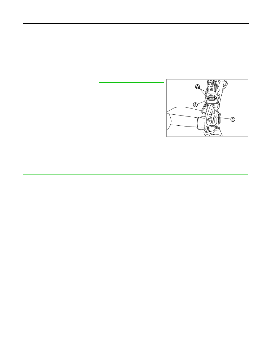
SEATBACK
SEATBACK : Removal and Installation
INFOID:0000000001837336
REMOVAL
CAUTION:
When removing and installing, use shop cloths to protect parts from damage.
1.
Remove seat back pad. Refer to
SE-152, "Removal and Installa-
2.
Remove screws (A).
3.
Disconnect seat sliding switch (seat back) connector.
4.
Remove seat sliding switch (seat back) (2) from seat back frame
(1).
INSTALLATION
Install in the reverse order of removal.
CAUTION:
Be sure to clamp the harness to the right place.
NOTE:
After installing the driver seat, perform additional service when removing battery negative terminal. Refer to
SE-7, "ADDITIONAL SERVICE WHEN REMOVING BATTERY NEGATIVE TERMINAL : Special Repair
Requirement"
JMJIA1099ZZ