Content .. 1087 1088 1089 1090 ..
Infiniti G37 Coupe. Manual - part 1089
SE-24
< FUNCTION DIAGNOSIS >
HEATED SEAT
HEATED SEAT
System Description
INFOID:0000000001694225
• Heated seat is a system that operates when ignition switch is in ON or START position.
• While operating the heated seat switch, seat cushion heater and seat back heater operate.
• Changing heated seat switch to LOW/HIGH position, depending on working heater number it is possible to
adjust the seat temperature.
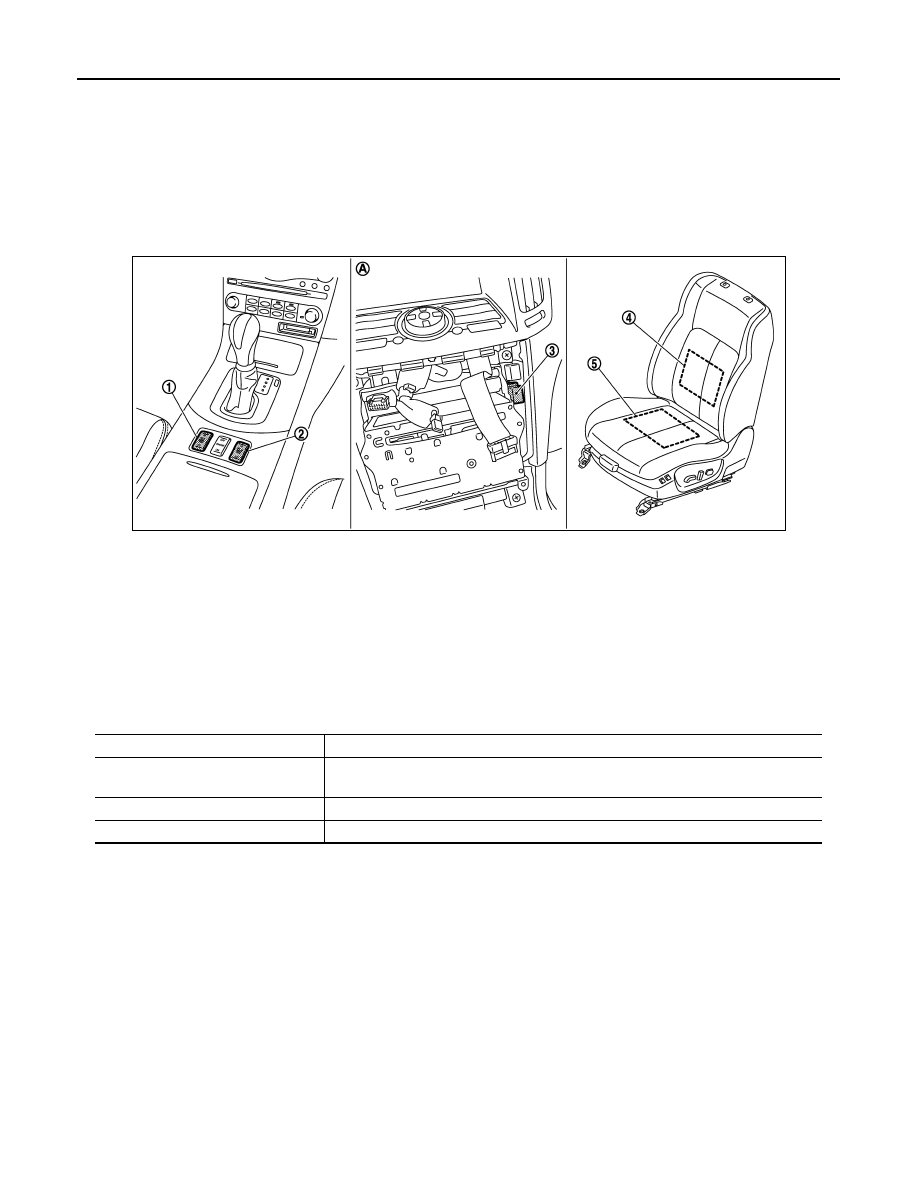
Component Parts Location
INFOID:0000000001694226
Component Description
INFOID:0000000001694227
JMJIA0191ZZ
1.
Heated seat switch (driver side)
M138: A/T models
M172: M/T models
2.
Heated seat switch (passenger side)
M140: A/T models
M173: M/T models
3.
Heated seat relay M70
4.
Seat back heater
5.
Seat cushion heater
B507: Driver side
B555: Passenger side
A.
View with cluster lid C is removed.
Item
Function
Heated seat switch
(driver side / passenger side)
• Power is supplied to each heater.
• Depending on LOW/HIGH position of switch, operating heater number is changeable.
Seat cushion heater
Built-in seat cushion, the heater operates with the power supplied by heater seat switch.
Seat back heater
Built-in seatback, the heater operates with the power supplied by heater seat switch.