Infiniti G37 Coupe. Manual - part 1021


  Index      Infiniti     Infiniti G37 Coupe - service repair manual 2008 year


Search            


Content   ..  1019  1020  1021  1022   ..


Infiniti G37 Coupe. Manual - part 1021


DOOR SWITCH

PWC-25

< COMPONENT DIAGNOSIS >

C

D

E

F

G

H

I

J

L

M

A

B

PWC

N

O

P

DOOR SWITCH

Description

INFOID:0000000001726453

Detects door open/close condition.

Component Function Check

INFOID:0000000001726454

1.

CHECK FUNCTION

With CONSULT-III

Check door switches (“DOOR SW-DR”, “DOOR SW-AS”) in Data Monitor” mode with CONSULT-III.

Is the inspection result normal?

YES

>> Door switch is OK.

NO

>> Refer to 

PWC-25, "Diagnosis Procedure"

.

Diagnosis Procedure

INFOID:0000000001726455

1.

CHECK DOOR SWITCH INPUT SIGNAL

1.

Turn ignition switch OFF.

2.

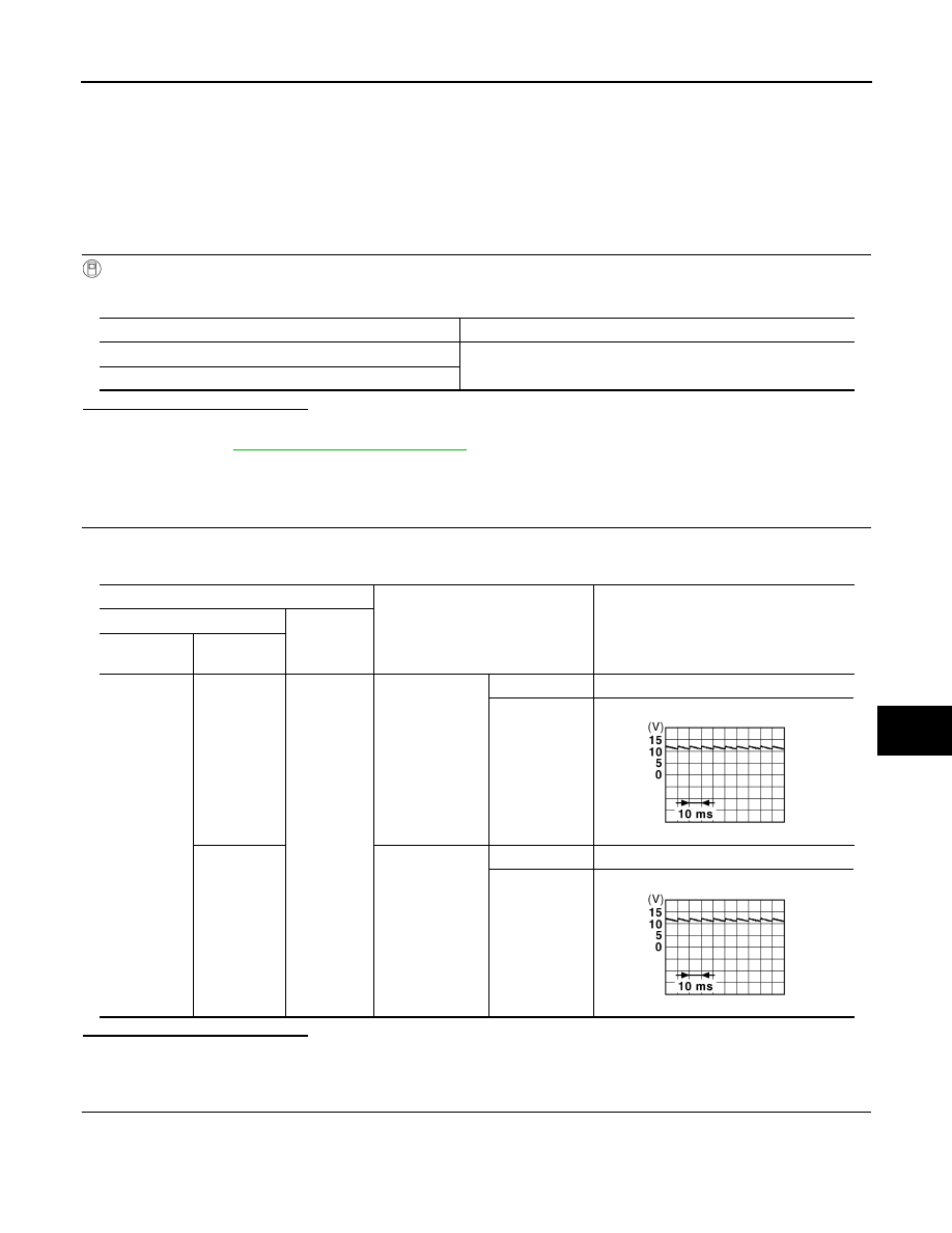
Check signal between BCM harness connector and ground with oscilloscope.

Is the inspection result normal?

YES

>> GO TO 4.

NO

>> GO TO 2.

2.

CHECK DOOR SWITCH CIRCUIT 

1.

Disconnect BCM connector and door switch connector.

2.

Check continuity between BCM harness connector and door switch harness connector.

Monitor item

Condition

DOOR SW-DR

CLOSE 

 OPEN: OFF 

 ON

DOOR SW-AS

Terminals

Door condition

Voltage (V)

(Approx.)

(+)

(–)

BCM

connector

Terminal

M123

150

Ground

Driver side

OPEN

0

CLOSE

124

Passenger side

OPEN

0

CLOSE

JPMIA0011GB

JPMIA0011GB

PWC-26

< COMPONENT DIAGNOSIS >

DOOR SWITCH

3.

Check continuity between BCM harness connector and ground.

Is the inspection result normal?

YES

>> GO TO 3.

NO

>> Repair or replace harness between BCM and door switch.

3.

CHECK DOOR SWITCH 

Refer to 

PWC-26, "Component Inspection"

.

Is the inspection result normal?

YES

>> GO TO 4.

NO

>> Replace malfunctioning door switch. Refer to 

DLK-238, "Removal and Installation"

.

4.

CHECK INTERMITTENT INCIDENT

Refer to 

GI-38, "Intermittent Incident"

.

>> INSPECTION END 

Component Inspection

INFOID:0000000001726456

1.

CHECK DOOR SWITCH

1.

Turn ignition switch OFF.

2.

Disconnect door switch connector.

3.

Check continuity between door switch terminal and ground.

Is the inspection result normal?

YES

>> INSPECTION END

NO

>> Replace malfunctioning door switch. Refer to 

DLK-238, "Removal and Installation"

.

BCM connector

Terminal

Door switch

connector

Terminal

Continuity 

M123

150

B16 (Driver side)

2

Existed

124

B216 (Passenger side)

BCM connector

Terminal

Ground

Continuity 

M123

150

Not existed

124

Terminal

Door switch condition

Continuity

Door switch

2

Ground part of door switch

Pressed

Not existed

Released

Existed

DOOR KEY CYLINDER SWITCH

PWC-27

< COMPONENT DIAGNOSIS >

C

D

E

F

G

H

I

J

L

M

A

B

PWC

N

O

P

DOOR KEY CYLINDER SWITCH

Description

INFOID:0000000001694018

Power window main switch detects condition of the door key cylinder switch and transmits to BCM as the
LOCK or UNLOCK signals. 

Component Function Check

INFOID:0000000001694019

1.

CHECK DOOR KEY CYLINDER SWITCH INPUT SIGNAL

 With CONSULT-III

Check (“KEY CYL LK-SW”, “KEY CYL UN-SW”) in “DATA MONITOR” mode for “POWER DOOR LOCK SYS-
TEM” with CONSULT-III. Refer to 

BCS-14, "DOOR LOCK : CONSULT-III Function (BCM - DOOR LOCK)"

.

Is the inspection result normal?

YES

>> Key cylinder switch is OK.

NO

>> Refer to 

PWC-27, "Diagnosis Procedure"

.

Diagnosis Procedure

INFOID:0000000001694020

1.

CHECK DOOR KEY CYLINDER SWITCH INPUT SIGNAL

1.

Turn ignition switch ON.

2.

Check voltage between driver side door lock assembly (key cylinder switch) harness connector and
ground.

Is the inspection result normal?

YES

>> GO TO 6.

NO

>> GO TO 2.

2.

CHECK POWER WINDOW MAIN SWITCH OUTPUT SIGNAL 

Check voltage between  power window main switch  harness connector and ground.

Is the inspection result normal?

YES

>> GO TO 3.

NO

>> Replace power window main switch.Refer to 

PWC-92, "Removal and Installation"

.

Monitor item

Condition

KEY CYL LK-SW

Lock

: ON

Neutral / Unlock

: OFF

KEY CYL UN-SW

Unlock

: ON

Neutral / Lock

: OFF

Terminals

Key position

Voltage (V)

(Approx.)

(+)

(–)

Driver side door lock assembly 
(key cylinder switch) connector

Terminal 

D15

6

Ground

Lock

0

Neutral / Unlock

5

5

Unlock

0

Neutral / Lock

5

Power window main switch connector

Terminal

(–)

Voltage (V)

(Approx.)

D8

6

Ground

5

7

PWC-28

< COMPONENT DIAGNOSIS >

DOOR KEY CYLINDER SWITCH

3.

CHECK DOOR KEY CYLINDER SIGNAL CIRCUIT

1.

Turn ignition switch OFF.

2.

Disconnect power window main switch connector and driver side door key lock assembly (key cylinder
switch) connector.

3.

Check continuity between power window main switch harness connector and driver side door lock assem-
bly (key cylinder switch) harness connector.

4.

Check continuity between power window main switch harness connector and ground.

Is the inspection result normal?

YES

>> GO TO 4.

NO

>> Repair or replace harness.

4.

CHECK DOOR KEY CYLINDER SWITCH GROUND CIRCUIT

Check continuity between driver side door lock assembly (key cylinder switch) harness connector and ground.

Is the inspection result normal?

YES

>> GO TO 5.

NO

>> Repair or replace harness.

5.

CHECK DOOR KEY CYLINDER SWITCH

Check door key cylinder switch. 
Refer to 

PWC-28, "Component Inspection"

.

Is the inspection result normal?

YES

>> GO TO 6.

NO

>> Replace driver side door lock assembly (key cylinder switch). Refer to 

DLK-234, "OUTSIDE HAN-

DLE : Removal and Installation"

.

6.

CHECK INTERMITTENT INCIDENT

Refer to 

GI-38, "Intermittent Incident"

.

>> INSPECTION END

Component Inspection

INFOID:0000000001694021

COMPONENT INSPECTION

1.

CHECK DOOR KEY CYLINDER SWITCH

1.

Turn ignition switch OFF.

2.

Disconnector driver side door lock assembly (key cylinder switch) connector.

3.

Check driver side door lock assembly (key cylinder switch).

Power window main switch connec-

tor

Terminal

Driver side door lock assembly (key cylinder 

switch) connector

Terminal

Continuity

D8

6

D15

6

Existed

7

5

Power window main switch connec-

tor

Terminal

Ground

Continuity 

D8

6

Not existed

7

Driver side door lock assembly (key cylinder 

switch) connector

Terminal

Ground

Continuity 

D15

4

Existed


Content   ..  1019  1020  1021  1022   ..