Infiniti G37 Coupe. Manual - part 93
AV
MULTI AV SYSTEM
AV-125
< FUNCTION DIAGNOSIS >
[BOSE AUDIO WITHOUT NAVIGATION]
C
D
E
F
G
H
I
J
K
L
M
B
A
O
P
FUNCTION DIAGNOSIS
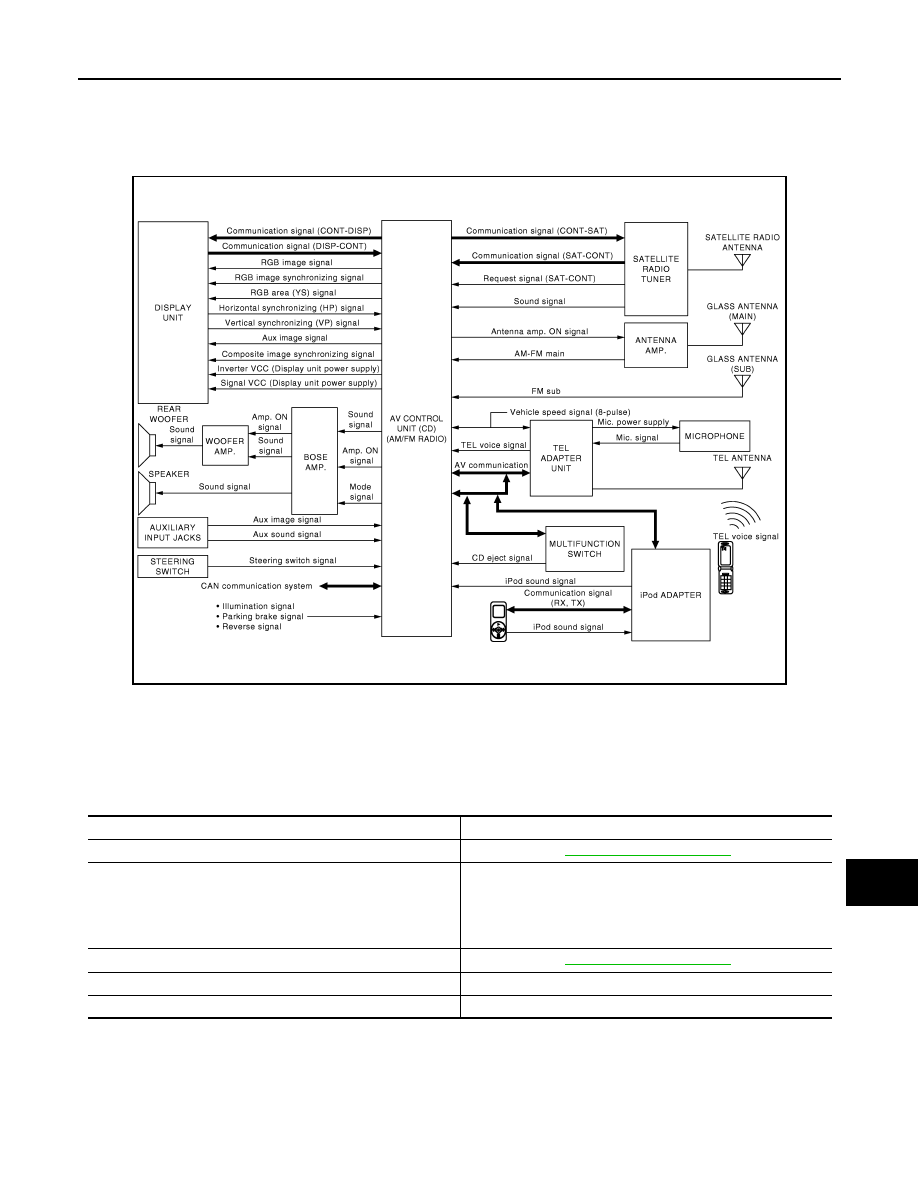
MULTI AV SYSTEM
System Diagram
INFOID:0000000001558983
NOTE:
The name MULTIFUNCTION SWITCH indicates the integration of PRESET SWITCH and MULTIFUNCTION
SWITCH virtually.
System Description
INFOID:0000000001558984
Multi AV system means that the following systems are integrated.
• AV control unit functions by transmitting/receiving data one by one with each unit (slave unit) that configures
them completely as a master unit by connecting between units that configure MULTI AV system with two AV
communication lines (H, L).
• Two AV communication lines (H, L) adopt a twisted pair line that is resistant to noise.
• AV control unit is connected by CAN communication, and it receives data signal from ECM, unified meter
and A/C amp. It computes and displays fuel economy information value with the obtained information. Trans-
JPNIA0404GB
System name
System explanation
AUDIO SYSTEM
VEHICLE INFORMATION SYSTEM
• Indicates the status of audio, climate control system, fuel econ-
omy and maintenance.
• AV control unit displays the fuel consumption status while re-
ceiving data signal through CAN communication from ECM,
unified meter and A/C amp and BCM.
HANDS-FREE PHONE SYSTEM
SATELLITE RADIO SYSTEM
Refer to “SATELLITE RADIO SYSTEM” shown below.
AUXILIARY INPUT SYSTEM
Refer to “AUXILIARY INPUT SYSTEM” shown below.