Infiniti G37 Coupe. Manual - part 25


  Index      Infiniti     Infiniti G37 Coupe - service repair manual 2008 year


Search            


Content   ..  23  24  25  26   ..


Infiniti G37 Coupe. Manual - part 25


ADP-94

< COMPONENT DIAGNOSIS >

PARKING BRAKE SWITCH

YES

>> GO TO 4.

NO

>> Adjust or replace parking brake switch.

4.

CHECK INTERMITTENT INCIDENT

Refer to 

GI-38, "Intermittent Incident"

.

Is the inspection result normal?

YES

>> Replace driver seat control unit.

NO

>> Repair or replace malfunctioning part.

Component Inspection

INFOID:0000000001693729

1.

CHECK PARKING BRAKE SWITCH

1.

Turn ignition switch OFF.

2.

Disconnect parking brake switch connector.

3.

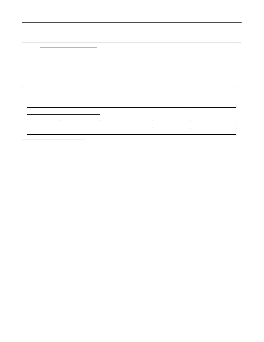
Check continuity between parking brake switch terminal and ground part of parking brake switch.

Is the inspection result normal?

YES

>> INSPECTION END

NO

>> Adjust or replace parking brake switch.

Terminal

Condition

Continuity

Parking brake switch

1

Ground part of

 parking brake switch

Parking brake

Applied

Existed

Release

Not existed

SLIDING SENSOR

ADP-95

< COMPONENT DIAGNOSIS >

C

D

E

F

G

H

I

K

L

M

A

B

ADP

N

O

P

SLIDING SENSOR

Description

INFOID:0000000001693734

• The sliding sensor is installed on the seat slide cushion frame.
• The pulse signal is transmitted to the driver seat control unit when sliding is operated.
• The driver seat control unit counts the pulse and calculates the sliding amount of the seat.

Component Function Check

INFOID:0000000001693735

1.

CHECK FUNCTION

1.

Select “SLIDE PULSE” in “Data Monitor” mode with CONSULT-III. 

2.

Check sliding sensor signal under the following conditions.

*1

: The value at the seat position attained when the battery is connected is considered to be 32768.

Is the indication normal?

YES

>> INSPECTION END

NO

>> Perform daiagnosis procedure. Refer to 

ADP-95, "Diagnosis Procedure"

.

Diagnosis Procedure

INFOID:0000000001693736

1.

CHECK SLIDING SENSOR SIGNAL

1.

Turn ignition switch ON.

2.

Read voltage signal between driver seat control unit harness connector and ground with oscilloscope.

Is the inspection result normal?

YES

>> GO TO 7.

NO

>> GO TO 2.

2.

CHECK SLIDING SENSOR CIRCUIT

1.

Turn ignition switch OFF.

2.

Disconnect driver seat control unit connector and sliding sensor connector.

3.

Check continuity between driver seat control unit harness connector and sliding sensor harness connec-
tor.

Monitor item

Condition

Valve

SLIDE PULSE

Seat sliding

Operate (forward)

Change (increase)

*1

Operate (backward)

Change (decrease)*

1

Release

No change

*1

Terminals

Condition

Voltage signal

(+)

(–)

Driver seat control unit 

connector

Terminal

B503

24

Ground

Seat sliding

Operate

Other than 
above

0 or 5

JMJIA0119ZZ

ADP-96

< COMPONENT DIAGNOSIS >

SLIDING SENSOR

4.

Check continuity between driver seat control unit harness connector and ground.

Is the inspection result normal?

YES

>> GO TO 3.

NO

>> Repair or replace harness.

3.

CHECK SLIDING SENSOR POWER SUPPLY

1.

Connect driver seat control unit connector.

2.

Turn ignition switch ON.

3.

Check voltage between sliding sensor harness connector and ground.

Is the inspection result normal?

YES

>> GO TO 5.

NO

>> GO TO 4.

4.

CHECK SLIDING SENSOR POWER SUPPLY CIRCUIT 

1.

Turn ignition switch OFF.

2.

Disconnect driver seat control unit connector.

3.

Check continuity between driver seat control unit harness connector and sliding sensor harness connec-
tor.

4.

Check continuity between driver seat control unit harness connector and ground.

Is the inspection result normal?

YES

>> GO TO 6.

NO

>> Repair or replace harness.

5.

CHECK SLIDING SENSOR GROUND 

1.

Turn ignition switch OFF.

2.

Disconnect driver seat control unit connector.

3.

Check continuity between driver seat control unit harness connector and sliding sensor harness connec-
tor.

Is the inspection result normal?

YES

>> GO TO 7.

Driver seat control unit

connector

Terminal

Sliding sensor

connector

Terminal

Continuity

B503

24

B526

24

Existed

Driver seat control unit

connector

Terminal

Ground

Continuity 

B503

24

Not existed

Terminals

Voltage (V)

(Approx.)

(+)

(–)

Sliding sensor connector

Terminal

B526

16

Ground

5

Driver seat

 control unit connector

Terminal

Sliding sensor

connector

Terminal

Continuity

B503

16

B526

16

Existed

Driver seat control unit 

connector

Terminal

Ground

Continuity 

B503

16

Not existed

Driver seat control unit

connector

Terminal

Sliding sensor

connector

Terminal

Continuity

B503

31

B526

31

Existed

SLIDING SENSOR

ADP-97

< COMPONENT DIAGNOSIS >

C

D

E

F

G

H

I

K

L

M

A

B

ADP

N

O

P

NO

>> Repair or replace harness.

6.

CHECK SEAT OPERATION

1.

Connect driver seat control unit connector and sliding sensor connector.

2.

Check seat operation (except sliding operation) with memory function.

Is the operation normal?

YES

>> Replace sliding sensor. (Built in seat slide cushion frame.)

NO

>> Replace driver seat control unit.

7.

CHECK INTERMITTENT INCIDENT

Refer to 

GI-38, "Intermittent Incident"

.

Is the inspection result normal?

YES

>> Replace driver seat control unit. Refer to 

ADP-236, "Removal and Installation"

.

NO

>> Repair or replace the malfunctioning part.


Content   ..  23  24  25  26   ..