Infiniti G35 (V35) Sedan. Manual - part 984


  Index      Infiniti     Infiniti G35 (V35) Sedan - service repair manual 2007 year


Search            


Content   ..  982  983  984  985   ..


Infiniti G35 (V35) Sedan. Manual - part 984


PB-2

< PREPARATION >

PREPARATION

PREPARATION

PREPARATION

Commercial Service Tool

INFOID:0000000000958480
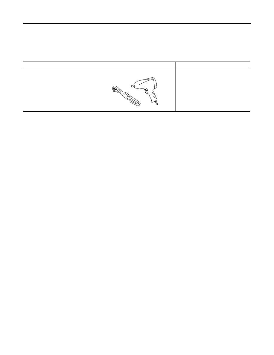
Tool name

Description

Power tool

Loosening bolts and nuts

PBIC0190E

PARKING BRAKE SYSTEM

PB-3

< ON-VEHICLE MAINTENANCE >

C

D

E

G

H

I

J

K

L

M

A

B

PB

N

O

P

ON-VEHICLE MAINTENANCE

PARKING BRAKE SYSTEM

PEDAL TYPE

PEDAL TYPE : Inspection and Adjustment

INFOID:0000000000958481

INSPECTION

Pedal Stroke

• Operate the parking brake pedal with a force of 196 N (20 kg, 44 lb). Check that the pedal stroke is within the

specified number of notches. (Check it by listening to clicks of ratchet.)

• When parking brake warning lamp turns ON, check that the pedal stroke is within the specified number of

notches. (Check it by listening to clicks of ratchet.)

Inspect Components

• Check each component for installation condition such as looseness.
• Check the device assembly for bend, damage and cracks. Replace if necessary.
• Check the cables and equalizer for wear, damage and cracks. Replace if necessary.
• Check the parking brake switch, and replace it if necessary. Refer to 

BRC-69, "Component Inspection"

.

ADJUSTMENT

• To perform adjustment operations, remove rear tires with power tool.

1.

Fix the disc rotor using wheel nuts.

2.

Release the parking brake pedal by turning the adjusting nut (1)
with a deep socket wrench and loosening the cable.

3.

Remove the adjusting hole plug from the disc rotor. Turn the
adjuster (1) in the direction (A) as shown in the figure using a
suitable tool until the disc rotor is locked. 

4.

Turn back the adjuster 5 or 6 notches from the locked position.

5.

Rotate the disc rotor to check that there is no drag. Install the
adjusting hole plug.

6.

Adjust the cable with the following procedure.

a.

Operate the parking brake pedal with a force of 490 N (50 kg,
110 lb) for 10 strokes or more. 

b.

Adjust the parking brake pedal stroke by turning the adjusting
nut with a deep socket wrench.

CAUTION:

Never reuse the adjusting nut if the nut is removed.

c.

Operate the parking brake pedal with a force of 196 N (20 kg, 44 lb). Check that the pedal stroke is within
the specified number of notches. (Check it by listening to clicks of ratchet.)

Standard

Number of notches

: Refer to 

PB-12, "Parking Brake Control"

Standard

Number of notches

: Refer to 

PB-12, "Parking Brake Control"

JPFIB0001ZZ

JPFIB0002ZZ

PB-4

< ON-VEHICLE MAINTENANCE >

PARKING BRAKE SYSTEM

d.

Rotate the disc rotor with the parking brake pedal released and check that there is no drag.

LEVER TYPE

LEVER TYPE : Inspection and Adjustment

INFOID:0000000000958482

INSPECTION

Lever Stroke

• Operate the parking brake lever with a force of 196 N (20 kg, 44 lb). Check that the lever stroke is within the

specified number of notches. (Check it by listening to the clicks of the ratchet.)

• When parking brake warning lamp turns ON, check that the lever stroke is within the specified number of

notches. (Check it by listening to the clicks of the ratchet.)

Inspect Components

• Check each component for installation condition such as looseness.
• Check the device assembly for bend, damage and cracks. Replace if necessary.
• Check the cables and equalizer for wear, damage and cracks. Replace if necessary.
• Check the parking brake switch, and replace it if necessary. Refer to 

BRC-69, "Component Inspection"

.

ADJUSTMENT

• To perform adjustment operations, remove rear tires with power tool.

1.

Fix the disc rotor using wheel nuts.

2.

Remove the coin pocket.

3.

Release the parking brake lever by turning the adjusting nut (1)
with a deep socket wrench and loosening the cable.

4.

Remove the adjusting hole plug from the disc rotor. Turn the
adjuster (1) in the direction (A) as shown in the figure using a
suitable tool until the disc rotor is locked. 

5.

Turn back the adjuster 5 or 6 notches from the locked position.

6.

Rotate the disc rotor to check that there is no drag. Install the
adjusting hole plug.

7.

Adjust the cable with the following procedure.

a.

Operate the parking brake lever with a force of 294 N (30 kg, 66
lb) for 10 strokes or more. 

b.

Adjust the parking brake lever stroke by turning the adjusting nut
with a deep socket wrench.

CAUTION:

Standard

Number of notches

: Refer to 

PB-12, "Parking Brake Control"

Standard

Number of notches

: Refer to 

PB-12, "Parking Brake Control"

Standard

Number of notches

: Refer to 

PB-12, "Parking Brake Control"

JPFIB0003ZZ

JPFIB0002ZZ

PARKING BRAKE SYSTEM

PB-5

< ON-VEHICLE MAINTENANCE >

C

D

E

G

H

I

J

K

L

M

A

B

PB

N

O

P

Never reuse the adjusting nut if the nut is removed.

c.

Operate the parking brake lever with a force of 196 N (20 kg, 44lb). Check that the lever stroke is within
the specified number of notches. (Check it by listening to the clicks of the ratchet.)

d.

Rotate the disc rotor with the parking brake lever released and check that there is no drag.

Standard

Number of notches

: Refer to 

PB-12, "Parking Brake Control"


Content   ..  982  983  984  985   ..