Infiniti G35 (V35) Sedan. Manual - part 957


  Index      Infiniti     Infiniti G35 (V35) Sedan - service repair manual 2007 year


Search            


Content   ..  955  956  957  958   ..


Infiniti G35 (V35) Sedan. Manual - part 957


MWI

FUEL LEVEL SENSOR SIGNAL CIRCUIT

MWI-55

< COMPONENT DIAGNOSIS >

C

D

E

F

G

H

I

J

K

L

M

B

N

A

O

P

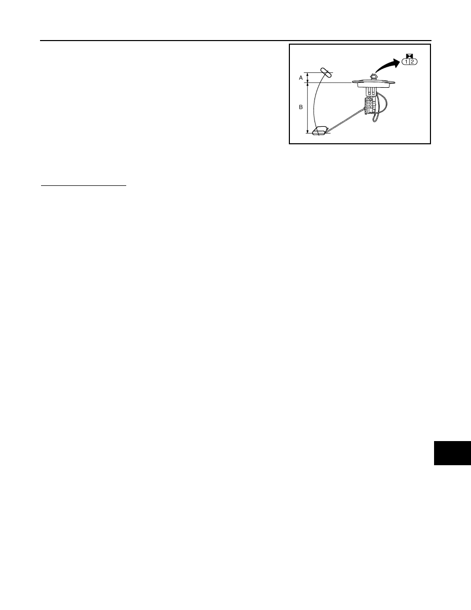
Inspect the resistance of fuel level sensor unit (sub).

Standard float position

Is inspection result OK?

YES

>> INSPECTION END

NO

>> Replace fuel level sensor unit (sub).

1 - 2

Full

: Approx. 3 

Empty

: Approx. 43 

JSNIA0111ZZ

Full (A) [mm (in)]

: Approx. 9 (0.35)

Empty (B) [mm (in)]

: Approx. 179 (7.05)

MWI-56

< COMPONENT DIAGNOSIS >

METER CONTROL SWITCH SIGNAL CIRCUIT

METER CONTROL SWITCH SIGNAL CIRCUIT

Description

INFOID:0000000000964402

Transmits the following signals to the combination meter.

Diagnosis Procedure

INFOID:0000000000964403

1.

CHECK METER CONTROL SWITCH INPUT SIGNAL

1.

Turn the ignition switch ON.

2.

Measure voltage between the following terminals of the combination meter.

Is the inspection result normal?

YES

>> INSPECTION END

NO

>> GO TO 2.

2.

CHECK METER CONTROL SWITCH SIGNAL CIRCUIT

1.

Turn the ignition switch OFF.

2.

Disconnect the combination meter and meter control switch connectors.

3.

Check continuity between combination meter harness connector M53 terminals 16, 36, 37, 39, 40, 38 and
meter control switch harness connector M54 terminals 7, 2, 1, 10, 9, 5.

4.

Check continuity between combination meter harness connector M53 terminals 16, 36, 37, 39, 40, 38 and
ground.

• Illumination control signal (+)

• Illumination control signal (–)

• Trip A/B reset signal

• Select switch signal

• Enter switch signal

Terminal 

No.

Condition

Voltage

36 - 16

When 

 switch is pressed

0 V

Other than the above

5 V

37 - 16

When 

 switch is pressed

0 V

Other than the above

5 V

38 - 16

When trip A/B reset switch is pressed

0 V

Other than the above

5 V

39 - 16

When 

 switch is pressed

0 V

Other than the above

5 V

40 - 16

When 

 switch is pressed

0 V

Other than the above

5 V

16 - 7

: Continuity should exist.

36 - 2

: Continuity should exist.

37 - 1

: Continuity should exist.

39 - 10

: Continuity should exist.

40 - 9

: Continuity should exist.

38 - 5

: Continuity should exist.

16 - Ground

: Continuity should not exist.

36 - Ground

: Continuity should not exist.

37 - Ground

: Continuity should not exist.

39 - Ground

: Continuity should not exist.

40 - Ground

: Continuity should not exist.

38 - Ground

: Continuity should not exist.

MWI

METER CONTROL SWITCH SIGNAL CIRCUIT

MWI-57

< COMPONENT DIAGNOSIS >

C

D

E

F

G

H

I

J

K

L

M

B

N

A

O

P

Is the inspection result normal?

YES

>> INSPECTION END

NO

>> Repair harness or connector.

Component Inspection

INFOID:0000000000964404

1.

CHECK METER CONTROL SWITCH UNIT

1.

Turn the ignition switch OFF.

2.

Disconnect the meter control switch connector.

3.

Check continuity of the meter control switch.

Is inspection result OK?

YES

>> INSPECTION END

NO

>> Replace the meter control switch.

Connector

Terminal No.

Operation and status

Continuity

M54

2

7

Press  

switch

Yes

Other than the above

No

1

7

Press  

switch

Yes

Other than the above

No

5

7

Press the trip A/B reset switch.

Yes

Other than the above

No

10

7

Press  

switch

Yes

Other than the above

No

9

7

Press  

switch

Yes

Other than the above

No

MWI-58

< COMPONENT DIAGNOSIS >

OIL PRESSURE SWITCH SIGNAL CIRCUIT

OIL PRESSURE SWITCH  SIGNAL CIRCUIT

Description

INFOID:0000000000964405

Detects the engine oil pressure and transmits the oil pressure switch signal to IPDM E/R.

Component Function Check

INFOID:0000000000964406

1.

CHECK UNIFIED METER AND A/C AMP. INPUT SIGNAL

Select the “Data Monitor” for the “METER/M&A” and check the “OIL W/L” monitor value.

>> INSPECTION END

Diagnosis Procedure

INFOID:0000000000964407

1.

CHECK OIL PRESSURE SWITCH CIRCUIT

1.

Turn ignition switch OFF.

2.

Disconnect IPDM E/R connector and oil pressure switch connector.

3.

Check continuity between IPDM E/R harness connector E6 terminal 75 and oil pressure switch harness
connector F37 terminal 1.

4.

Check continuity between IPDM E/R harness connector E6 terminal 75 and ground.

Is the inspection result normal?

YES

>> INSPECTION END

NO

>> Repair harness or connector.

Component Inspection

INFOID:0000000000964408

1.

CHECK OIL PRESSURE SWITCH UNIT

Check continuity between oil pressure switch and ground.

Is the inspection result normal?

YES

>> INSPECTION END

NO

>> Replace the oil pressure switch.

OIL W/L

Ignition switch ON

: ON

Engine running

: OFF

75 - 1

: Continuity should exist.

75 - Ground

: Continuity should not exist.

Condition

Oil pressure [kPa (kg/cm

2

, psi)]

Continuity

Engine stopped

Less than 29 (0.3, 4)

Yes

Engine running

More than 29 (0.3, 4) 

No

ELF0044D


Content   ..  955  956  957  958   ..