Infiniti G35 (V35) Sedan. Manual - part 937


  Index      Infiniti     Infiniti G35 (V35) Sedan - service repair manual 2007 year


Search            


Content   ..  935  936  937  938   ..


Infiniti G35 (V35) Sedan. Manual - part 937


DOOR MIRROR REMOTE CONTROL SWITCH

MIR-75

< COMPONENT DIAGNOSIS >

[WITHOUT ADP]

C

D

E

F

G

H

I

J

K

M

A

B

MIR

N

O

P

Is the inspection result normal?

YES

>> GO TO 4.

NO

>> GO TO 3.

3.

CHECK HARNESS CONTINUITY

1.

Turn ignition switch OFF.

2.

Disconnect door mirror remote control switch connector.

3.

Check continuity between mirror control switch connector and fuse block.

4.

Check continuity between mirror control switch connector and ground

Is the inspection result normal?

YES

>> GO TO 6.

NO

>> Repair or replace harness.

4.

CHECK GROUND CIRCUIT

1.

Turn ignition switch OFF.

2.

Disconnect door mirror remote control switch connector.

3.

Check continuity between mirror control switch connector and ground.

Is the inspection result normal?

YES

>> GO TO 5.

NO

>> Repair or replace harness.

5.

CHECK DOOR MIRROR REMOTE CONTROL SWITCH

Check door mirror remote control switch.
Refer to 

MIR-75, "Component Inspection"

.

Is the inspection result normal?

YES

>> Refer to 

GI-39, "Intermittent Incident"

.

NO

>> Replace door mirror remote control switch. Refer to 

MIR-98, "Removal and Installation"

.

6.

CHECK INTERMITTENT INCIDENT

Check intermittent incident.
Refer to 

GI-39, "Intermittent Incident"

.

Is the inspection result normal?

YES

>>

Check the following.

• Battery power supply circuit
• Fuse block (J/B)

NO

>> Repair or replace the malfunctioning parts.

Component Inspection

INFOID:0000000000962363
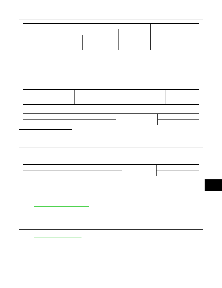
Terminals

Voltage (V)

(Approx.)

(+)

(-)

 Door mirror remote control switch con-

nector

Terminal

D7

7

Ground

Battery voltage

Door mirror remote control switch 

connector

Terminal

Fuse block (J/B)

Terminal

Continuity

D7

7

M1

5A

Existed

Door mirror remote control switch connector 

Terminal

Ground

Continuity

D7

7

Not existed

 Door mirror remote control switch connector

Terminal

Ground

Continuity

D7

1

Existed

MIR-76

< COMPONENT DIAGNOSIS >

[WITHOUT ADP]

DOOR MIRROR REMOTE CONTROL SWITCH

1.

CHECK DOOR MIRROR REMOTE CONTROL SWITCH

Check door mirror remote control switch.

[Driver side]

[Passenger side]

Is the inspection result normal?

YES

>> INSPECTION END.

NO

>> Replace door mirror remote control switch. Refer to 

MIR-98, "Removal and Installation"

.

Terminal

Mirror switch condition

Continuity

Door mirror remote control switch

10

7

RIGHT / DOWN

Existed

Other than above

Not existed

14

LEFT

Existed

Other than above

Not existed

16

UP

Existed

Other than above

Not existed

Terminal

Mirror switch condition

Continuity

Door mirror remote control switch

12

7

RIGHT / DOWN

Existed

Other than above

Not existed

13

LEFT

Existed

Other than above

Not existed

15

UP

Existed

Other than above

Not existed

DOOR MIRROR MOTOR

MIR-77

< COMPONENT DIAGNOSIS >

[WITHOUT ADP]

C

D

E

F

G

H

I

J

K

M

A

B

MIR

N

O

P

DOOR MIRROR MOTOR

Description

INFOID:0000000000962364

It supplies electric power to door mirror motor with mirror switch and LH/RH control switch.

Component Function Check

INFOID:0000000000962365

1.

CHECK DOOR MIRROR MOTOR FUNCTION

Does motor operate normally during mirror switch operation.

Is the inspection result normal?

YES

>> Door mirror motor function is OK.

NO

>> Refer to 

MIR-77, "Diagnosis Procedure"

.

Diagnosis Procedure

INFOID:0000000000962366

1.

CHECK DOOR MIRROR MOTOR INPUT SIGNAL

1.

Turn ignition switch ON.

2.

Check voltage between door mirror connector and ground.

Is the inspection result normal?

YES

>> GO TO 3.

NO

>> GO TO 2.

2.

CHECK HARNESS CONTINUITY

1.

Turn ignition switch OFF.

2.

Disconnect door mirror remote control switch connector and door mirror connector.

3.

Check continuity between door mirror remote control switch connector and door mirror connector.

-

[Driver side]

[Passenger side]

-

Check continuity between automatic drive positioner control unit connector and ground.

Terminals

Mirror switch

Condition

Voltage (V)

(Approx.)

(+)

(–)

Door mirror 

connector

Terminal

D3 (Driver side)

D33 (Passenger side)

5

Ground

UP

Battery voltage

Other than above

0

6

LEFT

Battery voltage

Other than above

0

7

DOWN / RIGHT

Battery voltage

Other than above

0

Door mirror remote control 

switch connector

Terminal

Door mirror (driver side) con-

nector

Terminal

Continuity

D7

10

D3

7

Existed

16

5

14

6

Door mirror remote control 

switch connector

Terminal

Door mirror (passenger side) 

connector

Terminal

Continuity

D7

12

D33

7

Existed

15

5

13

6

MIR-78

< COMPONENT DIAGNOSIS >

[WITHOUT ADP]

DOOR MIRROR MOTOR

[Driver side]

[Passenger side]

Is the inspection result normal?

YES

>> Refer to 

GI-39, "Intermittent Incident"

.

NO

>> Repair or replace harness.

3.

CHECK DOOR MIRROR MOTOR

Check door mirror motor.
Refer to 

MIR-78, "Component Inspection"

.

Is the inspection result normal?

YES

>>  Refer to 

GI-39, "Intermittent Incident"

.

NO

>> Replace door mirror. Refer to 

MIR-97, "Removal and Installation"

.

Component Inspection

INFOID:0000000000962367

1.

CHECK DOOR MIRROR MOTOR-I

Check that door mirror motor does not trap foreign objects and does not have any damage.
Refer to 

MIR-97, "Exploded View"

.

Is the inspection result normal?

YES

>> GO TO 2.

NO

>> Replace door mirror. Refer to 

MIR-97, "Removal and Installation"

.

2.

CHECK DOOR MIRROR MOTOR-II

1.

Turn ignition switch OFF.

2.

Disconnect door mirror connector.

3.

Apply 12V to each power supply terminal of door mirror motor.

Is the inspection result normal?

YES

>> INSPECTION END.

NO

>> Replace door mirror. Refer to 

MIR-97, "Removal and Installation"

.

Door mirror remote control switch con-

nector

Terminal

Ground

Continuity

D7

10

Not existed

16

14

Door mirror remote control switch con-

nector

Terminal

Ground

Continuity

D7

12

Not existed

15

13

Door mirror connector

Terminal

Operational direction

(+)

(–)

D3 (Driver side)

D33 (Passenger side)

7

6

RIGHT

6

7

LEFT

5

7

UP

7

5

DOWN


Content   ..  935  936  937  938   ..