Infiniti G35 (V35) Sedan. Manual - part 907
LU-12
< ON-VEHICLE REPAIR >
OIL FILTER BRACKET
ON-VEHICLE REPAIR
OIL FILTER BRACKET
AWD
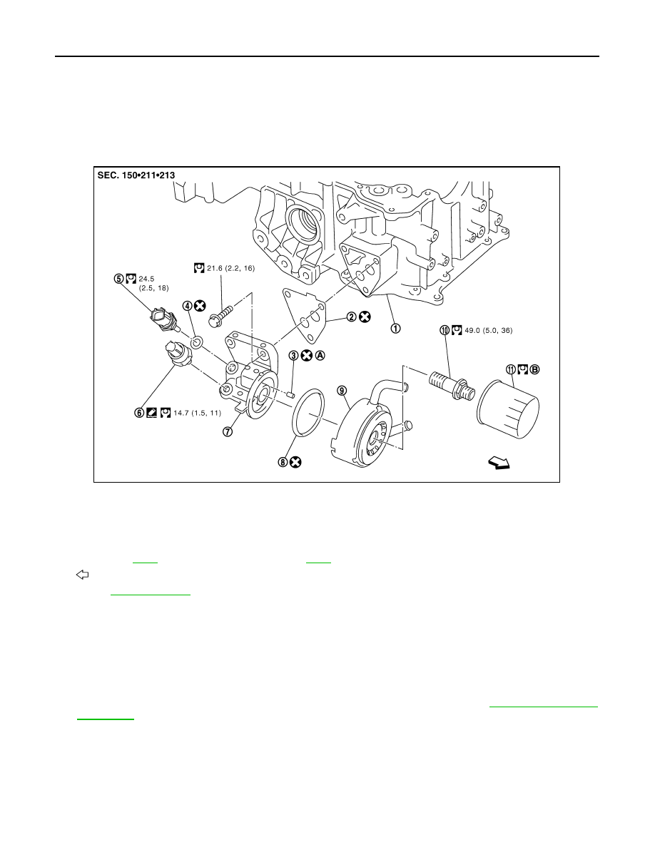
AWD : Exploded View
INFOID:0000000000956315
AWD : Removal and Installation
INFOID:0000000000956316
REMOVAL
WARNING:
Be careful not to get burn yourself, as engine oil may be hot.
1.
Remove engine undercover with power tool.
2.
Using the oil filter wrench [SST: KV10115801 (J38956)], remove oil filter. Refer to
.
CAUTION:
Do not spill engine oil on drive belt.
3.
Remove connector bolt, and then oil cooler with water hoses connected.
4.
Disconnect oil pressure switch harness connector and oil temperature sensor harness connector.
5.
Remove oil filter bracket from oil pan (upper).
6.
Remove oil pressure switch and oil temperature sensor from oil filter bracket.
1.
Oil pan (upper)
2.
Gasket
3.
Relief valve
4.
Washer
5.
Oil temperature sensor
6.
Oil pressure switch
7.
Oil filter bracket
8.
O-ring
9.
Oil cooler
10.
Connector bolt
11.
Oil filter
A.
Refer to
B.
: Engine front
Refer to
for symbol marks in the figure.
JPBIA0245GB