Infiniti G35 (V35) Sedan. Manual - part 842
LAN
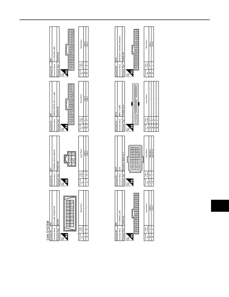
CAN COMMUNICATION SYSTEM
LAN-37
< COMPONENT DIAGNOSIS >
[CAN]
C
D
E
F
G
H
I
J
K
L
B
A
O
P
N
JCMWA0015GB
|
|
|
LAN CAN COMMUNICATION SYSTEM LAN-37 < COMPONENT DIAGNOSIS > [CAN] C D E F G H I J K L B A O P N JCMWA0015GB |