Infiniti G35 (V35) Sedan. Manual - part 824
INT-20
< ON-VEHICLE REPAIR >
FLOOR TRIM
FLOOR TRIM
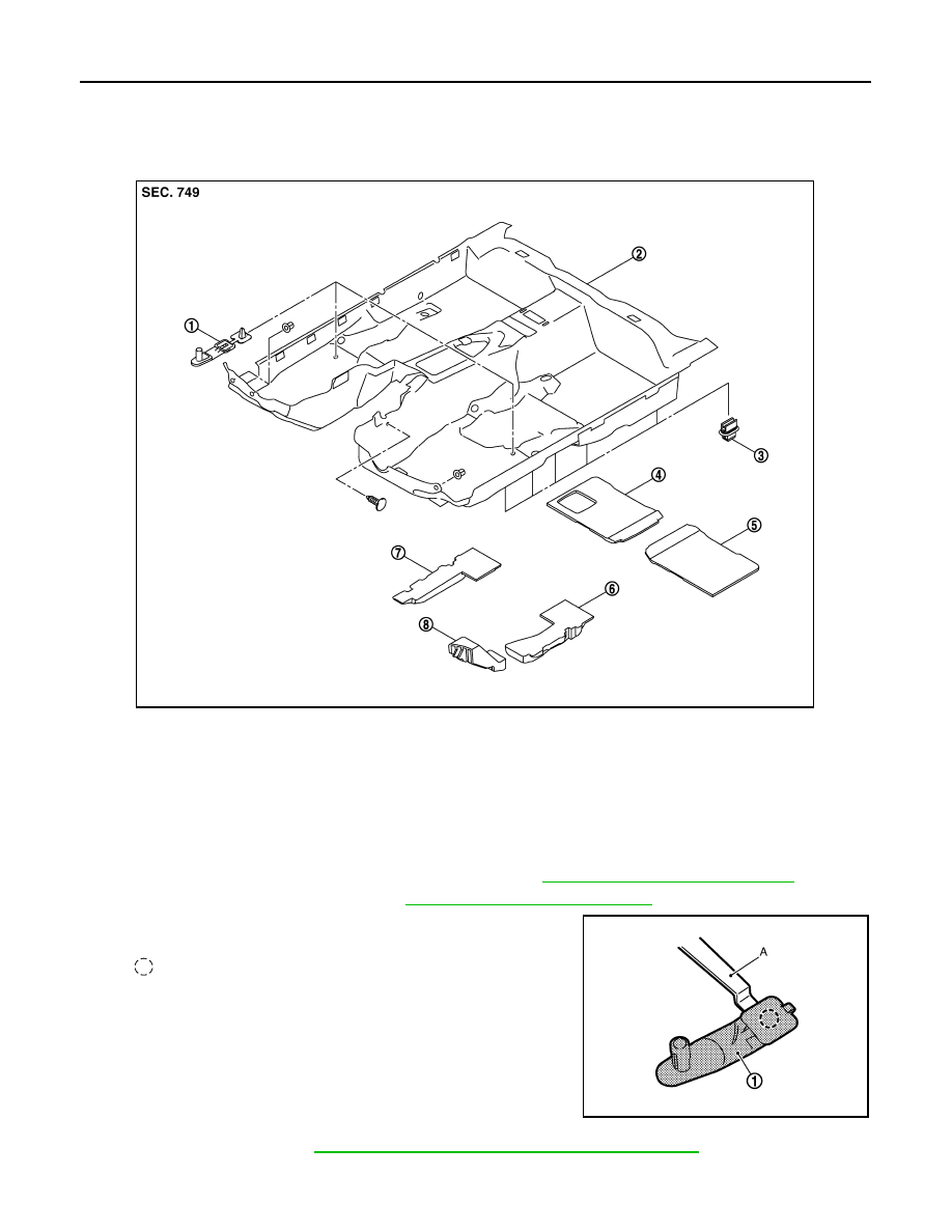
Exploded View
INFOID:0000000000960440
Removal and Installation
INFOID:0000000000960441
REMOVAL
1.
Remove front seat (LH/RH) and rear seat cushion. Refer to
SE-105, "Removal and Installation"
.
2.
Remove accelerator pedal pad. Refer to
ACC-3, "Removal and Installation"
.
3.
Disengage clip of floor hook (1) with remover tool (A).
4.
Remove foot grille. Refer to
VTL-50, "FOOT GRILLES : Removal and Installation"
1.
Floor hook
2.
Floor trim
3.
Fixing clip
4.
Rear floor spacer (RH)
5.
Rear floor spacer (LH)
6.
Front floor spacer (LH)
7.
Front floor spacer (RH)
8.
Footrest
JMJIA0069GB
: Clip
JMJIA0092GB