Infiniti G35 (V35) Sedan. Manual - part 795


  Index      Infiniti     Infiniti G35 (V35) Sedan - service repair manual 2007 year


Search            


Content   ..  793  794  795  796   ..


Infiniti G35 (V35) Sedan. Manual - part 795


INL-8

< FUNCTION DIAGNOSIS >

INTERIOR ROOM LAMP CONTROL SYSTEM

Component Description

INFOID:0000000000962568
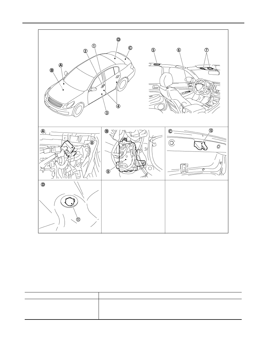
1.

Key cylinder switch

2.

Request switch

3.

Step lamp

4.

Door switch

5.

Personal lamp

6.

Central door lock switch

7.

Map lamp

8.

Remote keyless entry receiver

9.

BCM

10. Trunk room lamp switch

11. Trunk room lamp

A.

Behind glove box

B.

Dash side finisher (Passenger side)

C.

Trunk lid lock assembly

D.

Trunk room upward

JPLIA0038ZZ

Part

Description

BCM

• Activates the interior room lamp timer depending on the vehicle condition to turn the 

interior room lamp ON/OFF.

• Turns the trunk room lamp ON /OFF according to the trunk room lamp switch status.
• Turns the step lamp ON /OFF according to any door switch status.

INTERIOR ROOM LAMP BATTERY SAVER SYSTEM

INL-9

< FUNCTION DIAGNOSIS >

C

D

E

F

G

H

I

J

K

M

A

B

INL

N

O

P

INTERIOR ROOM LAMP BATTERY SAVER SYSTEM

System Diagram

INFOID:0000000000962569

System Description

INFOID:0000000000962570

OUTLINE

• Interior room lamp battery saver is controlled by BCM.
• BCM turns applicable lamps OFF depending on the vehicle condition. This function prevents the battery

from over-discharging if the driver neglect turning OFF the any lamps.

Applicable lamps

• Map lamp
• Personal lamp
• Step lamp
• Trunk room lamp
• Vanity mirror lamp

INTERIOR ROOM LAMP BATTERY SAVER FANCTION

• When the ignition switch is turned OFF, BCM operates the timer for a period of time to cut the interior room

lamp power supply.

• BCM restart the timer when any of the following signals changes while operating the timer.
- Ignition switch status
- Door switch signal (ALL)
- Door lock/unlock signal (Remote keyless entry receiver, each request switch, key cylinder lock/unlock

switch, central door lock/unlock switch)

- Trunk loom lamp switch signal
- Key switch signal (Key slot)
• BCM provides the interior room lamp power supply continuously when the ignition switch position is other

than OFF.

NOTE:
Each function of interior room lamp battery saver can be set by CONSULT-III Refer to 

INL-15, "BATTERY

SAVER : CONSULT-III Function (BCM - BATTERY SAVER)"

.

Component Parts Location

INFOID:0000000000962571

JPLIA0091GB

INL-10

< FUNCTION DIAGNOSIS >

INTERIOR ROOM LAMP BATTERY SAVER SYSTEM

Component Description

INFOID:0000000000962572

1.

Key cylinder switch

2.

Request switch

3.

Step lamp

4.

Door switch

5.

Personal lamp

6.

Central door lock switch

7.

Vanity mirror lamp

8.

Map lamp

9.

Remote keyless entry receiver

10. BCM

11.

Trunk room lamp switch

12.

Trunk room lamp

A.

Behind glove box

B.

Dash side finisher (Passenger side)

C.

Trunk lid lock assembly

D.

Trunk room upward

JPLIA0039ZZ

Part

Description

BCM

Operates the interior room lamp battery saver depending on the vehicle condition to 
cut the interior room lamp power supply. 

ILLUMINATION CONTROL SYSTEM

INL-11

< FUNCTION DIAGNOSIS >

C

D

E

F

G

H

I

J

K

M

A

B

INL

N

O

P

ILLUMINATION CONTROL SYSTEM

System Diagram

INFOID:0000000000962573

System Description

INFOID:0000000000962574

OUTLINE

Each illumination lamp is controlled by each function of BCM, IPDM E/R and combination meter.

Control by BCM

• Combination switch reading function
• Headlamp control function

Control by IPDM E/R

• Relay control function

Control by combination meter

• Meter illumination control function (Refer to 

MWI-24, "METER ILLUMINATION CONTROL : System Dia-

gram"

.)

ILLUMINATION CONTROL

• BCM detects the combination switch condition by the combination switch reading function.
• BCM transmits position light request signal to IPDM E/R and combination meter (through the unified meter

and A/C amp.) according to tail lamp ON condition.

Tail lamp ON condition

- Lighting switch 1ST
- Lighting switch 2ND
- Lighting switch AUTO, and the auto light function ON judgment (With auto light system)
• IPDM E/R turns the integrated tail lamp relay ON according to position light request signal. It provides the

power supply to each illumination lamp. 

• Combination meter enters in the nighttime mode according to position light request signal. Under the night-

time mode the combination meter controls the illuminance by controlling the each illumination lamp (ground
side).

Component Parts Location

INFOID:0000000000962575

JPLIA0092GB


Content   ..  793  794  795  796   ..