Infiniti G35 (V35) Sedan. Manual - part 780


  Index      Infiniti     Infiniti G35 (V35) Sedan - service repair manual 2007 year


Search            


Content   ..  778  779  780  781   ..


Infiniti G35 (V35) Sedan. Manual - part 780


HAC-92

< COMPONENT DIAGNOSIS >

[AUTOMATIC AIR CONDITIONER]

MAGNET CLUTCH

8.

CHECK ECM INPUT (FAN ON) SIGNAL

Check FAN ON/OFF signal. Refer to 

HAC-49, "WITHOUT LEFT AND RIGHT VENTILATION TEMPERATURE

SEPARATELY CONTROL SYSTEM : CONSULT-III Function"

.

Is the inspection result normal?

YES

>> GO TO 9.

NO

>> Repair harness or connector.

9.

CHECK CAN COMMUNICATION

Check CAN communication. Refer to 

BCS-43, "Reference Value"

.

• ECM – IPDM E/R
• ECM – Unified meter and A/C amp.

Is the inspection result normal?

YES

>> Replace ECM.

NO

>> Repair or replace malfunctioning part(s).

Component Inspection

INFOID:0000000000959951

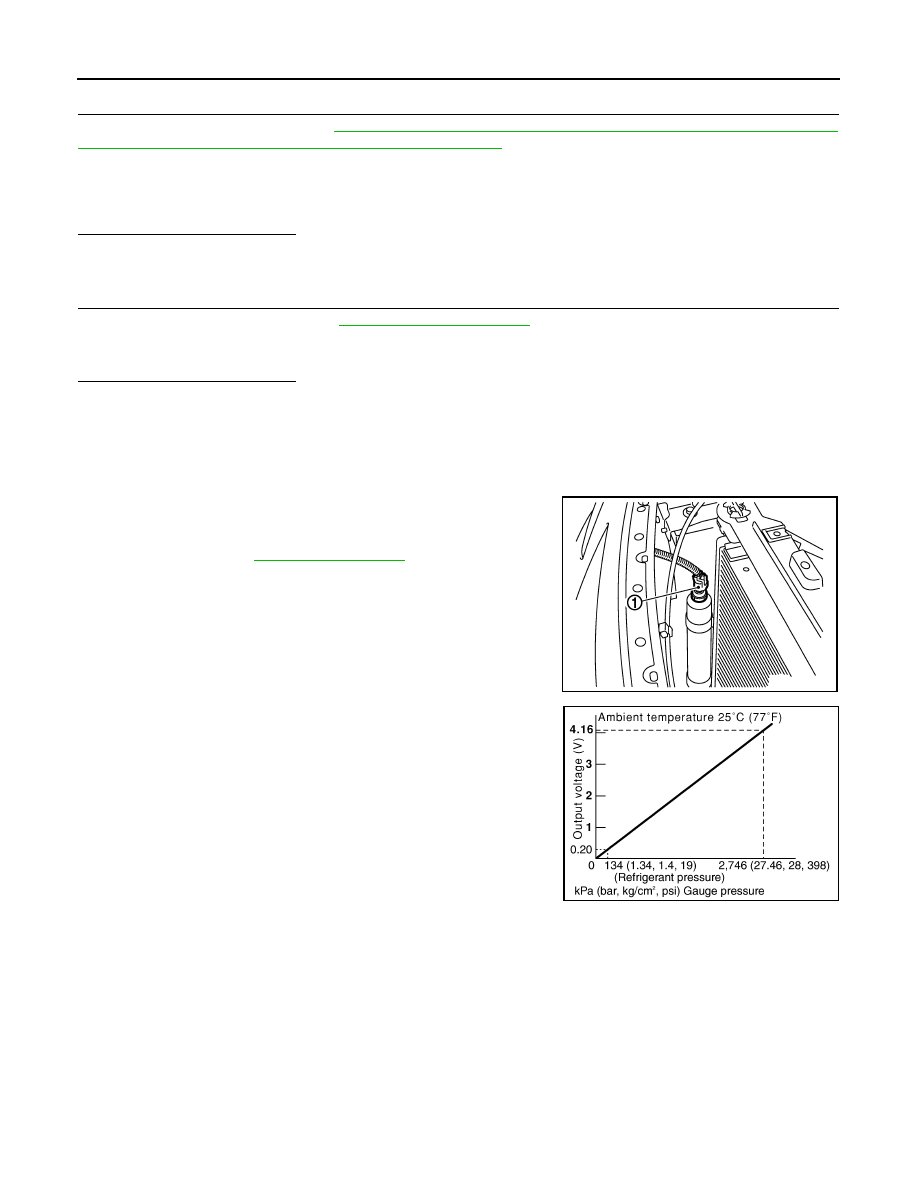
Refrigerant Pressure Sensor

The refrigerant pressure sensor (1) is attached to the liquid tank.
Make sure that the A/C refrigerant pressure and the sensor output
voltage are within the specified range as shown in the A/C operating
condition figure. Refer to 

EC-479, "Description"

.

FAN SW ON

: HEATER FAN SW ON

FAN SW OFF

: HEATER FAN SW OFF

JSIIA0045ZZ

SJIA1841E

AMBIENT SENSOR

HAC-93

< COMPONENT DIAGNOSIS >

[AUTOMATIC AIR CONDITIONER]

C

D

E

F

G

H

J

K

L

M

A

B

HAC

N

O

P

AMBIENT SENSOR

Description

INFOID:0000000000959952

COMPONENT DESCRIPTION

Ambient Sensor

The ambient sensor (1) is attached on the radiator core support (left
side). It detects ambient temperature and converts it into a resis-
tance value which is then input into the unified meter and A/C amp.

Ambient Sensor Circuit

AMBIENT TEMPERATURE INPUT PROCESS

The unified meter and A/C amp. includes a processing circuit for the ambient sensor input. However, when the
temperature detected by the ambient sensor increases quickly, the processing circuit retards the unified meter
and A/C amp. function. It only allows the unified meter and A/C amp. to recognize an ambient temperature
increase of 0.33

°

C (0.6

°

F) per 100 seconds.

As an example, consider stopping for a few minutes after high speed driving. Although the actual ambient tem-
perature has not changed, the temperature detected by the ambient sensor will increase. This is because the
heat from the engine compartment can radiate to the front bumper area, location of the ambient sensor.

Component Function Check

INFOID:0000000000959953

1.

PERFORM SELF-DIAGNOSIS STEP-2

Perform self-diagnosis STEP-2. Refer to 

HAC-44, "WITHOUT LEFT AND RIGHT VENTILATION TEMPERA-

TURE SEPARATELY CONTROL SYSTEM : Diagnosis Description"

 (Without left and right ventilation tempera-

ture separately control system) or 

HAC-50, "WITH LEFT AND RIGHT VENTILATION TEMPERATURE

SEPARATELY CONTROL SYSTEM : Diagnosis Description"

 (With left and right ventilation temperature sepa-

rately control system), see No. 1 to 2.
21 or 

21 is displayed.

YES

>> Go to Diagnosis Procedure. Refer to 

HAC-93, "Diagnosis Procedure"

.

NO

>> END.

Diagnosis Procedure

INFOID:0000000000959954

1.

CHECK VOLTAGE BETWEEN AMBIENT SENSOR AND GROUND

1.

Disconnect ambient sensor connector.

2.

Turn ignition switch ON.

3.

Check voltage between ambient sensor harness connector E76 terminal 1 and ground.

JSIIA0046ZZ

RJIA4088E

HAC-94

< COMPONENT DIAGNOSIS >

[AUTOMATIC AIR CONDITIONER]

AMBIENT SENSOR

Is the inspection result normal?

YES

>> GO TO 2.

NO

>> GO TO 4.

2.

CHECK CIRCUIT CONTINUITY BETWEEN AMBIENT SENSOR AND UNIFIED METER AND A/C AMP. 

1.

Turn ignition switch OFF.

2.

Disconnect unified meter and A/C amp. connector.

3.

Check continuity between ambient sensor harness connector E76 terminal 2 and unified meter and A/C
amp. harness connector M67 terminal 61.

Is the inspection result normal?

YES

>> GO TO 3.

NO

>> Repair harness or connector.

3.

CHECK AMBIENT SENSOR

Refer to 

HAC-94, "Component Inspection"

.

Is the inspection result normal?

YES

>> Replace unified meter and A/C amp.

NO

>> Replace ambient sensor.

4.

CHECK CIRCUIT CONTINUITY BETWEEN AMBIENT SENSOR AND UNIFIED METER AND A/C AMP.

1.

Turn ignition switch OFF.

2.

Disconnect unified meter and A/C amp. connector.

3.

Check continuity between ambient sensor harness connector E76 terminal 1 and unified meter and A/C
amp. harness connector M67 terminal 45.

4.

Check continuity between ambient sensor harness connector E76 terminal 1 and ground.

Is the inspection result normal?

YES

>> Replace unified meter and A/C amp.

NO

>> Repair harness or connector.

Component Inspection

INFOID:0000000000959955

(+)

(

)

Voltage

Ambient sensor

Connector

Terminal

E76

1

Ground

Approx. 5 V

(+)

(

)

Continuity

ambient sensor

Unified meter and A/C amp.

Connector

Terminal

Connector

Terminal

E76

2

M67

61

Continuity should exist

(+)

(

)

Continuity

Ambient sensor

Unified meter and A/C amp.

Connector

Terminal

Connector

Terminal

E76

1

M67

45

Continuity should exist

(+)

(

)

Continuity

Ambient sensor

Connector

Terminal

E76

1

Ground

Continuity should not exist

AMBIENT SENSOR

HAC-95

< COMPONENT DIAGNOSIS >

[AUTOMATIC AIR CONDITIONER]

C

D

E

F

G

H

J

K

L

M

A

B

HAC

N

O

P

After disconnecting ambient sensor (1) connector E76, measure
resistance between terminals 1 and 2 at sensor side. Refer to table
below.

If NG, replace ambient sensor.

Temperature 

°

C (

°

F)

Resistance k


15 (5)

12.73


10 (14)

9.92


5 (23)

7.80

0 (32)

6.19

5 (41)

4.95

10 (50)

3.99

15 (59)

3.24

20 (68)

2.65

25 (77)

2.19

30 (86)

1.81

35 (95)

1.51

40 (104)

1.27

45 (113)

1.07

JSIIA0047ZZ


Content   ..  778  779  780  781   ..